
Regular Block Models
A regular block model has blocks that are all the same size and are never divided.
Regular block models can be exported in CSV, Datamine, Surpac and Geosoft Voxel formats.
The rest of this topic describes:
- Creating a Regular Block Model
- Selecting Evaluations
- Selecting Meshes for Calculating Proportions
- Exporting Regular Block Models
Creating a Regular Block Model
To create a new regular block model, right-click on the Block Models folder and select New Block Model. In the window that appears, select the Regular Block Model option.
The New Regular Block Model window will appear, together with a set of controls that will help you set the size, location and orientation of the model in the scene:
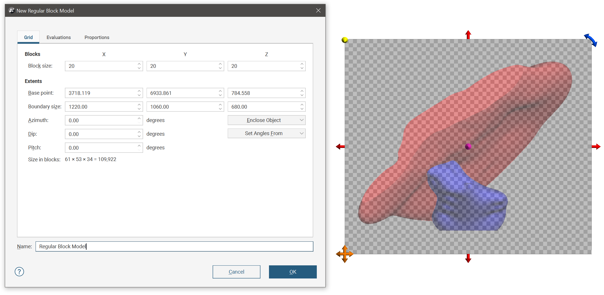
The block model is defined from its Base point, and the reference centroid is the Base point plus one half the Block size. Block models extents always include complete blocks, and when changes are made to the Block size parameter, the model’s extents will be enlarged to fit the Block size.
If you know the values you wish to use for the model’s Extents, enter them in New Block Model window. You can also:
- Use the controls in the scene to set the extents.
- The orange handle sets the Base point.
- The red handles adjust the size of the boundary.
- The blue handle adjusts the Azimuth.
- Use another object’s extents. Select the object from the Enclose Object list.
You can create a tilted block model by adjusting the Azimuth, Dip and Pitch angles, or you can Set Angles From the slicer or moving plane.
It is a good idea to use larger values for the Block size as processing time for large models can be considerable. Once you have created a block model, you can change its properties to provide more detail.
Once you have set evaluations and proportions, enter a Name for the block model and click OK. The model will appear under the Block Models folder. You can make changes to it by double-clicking on it.
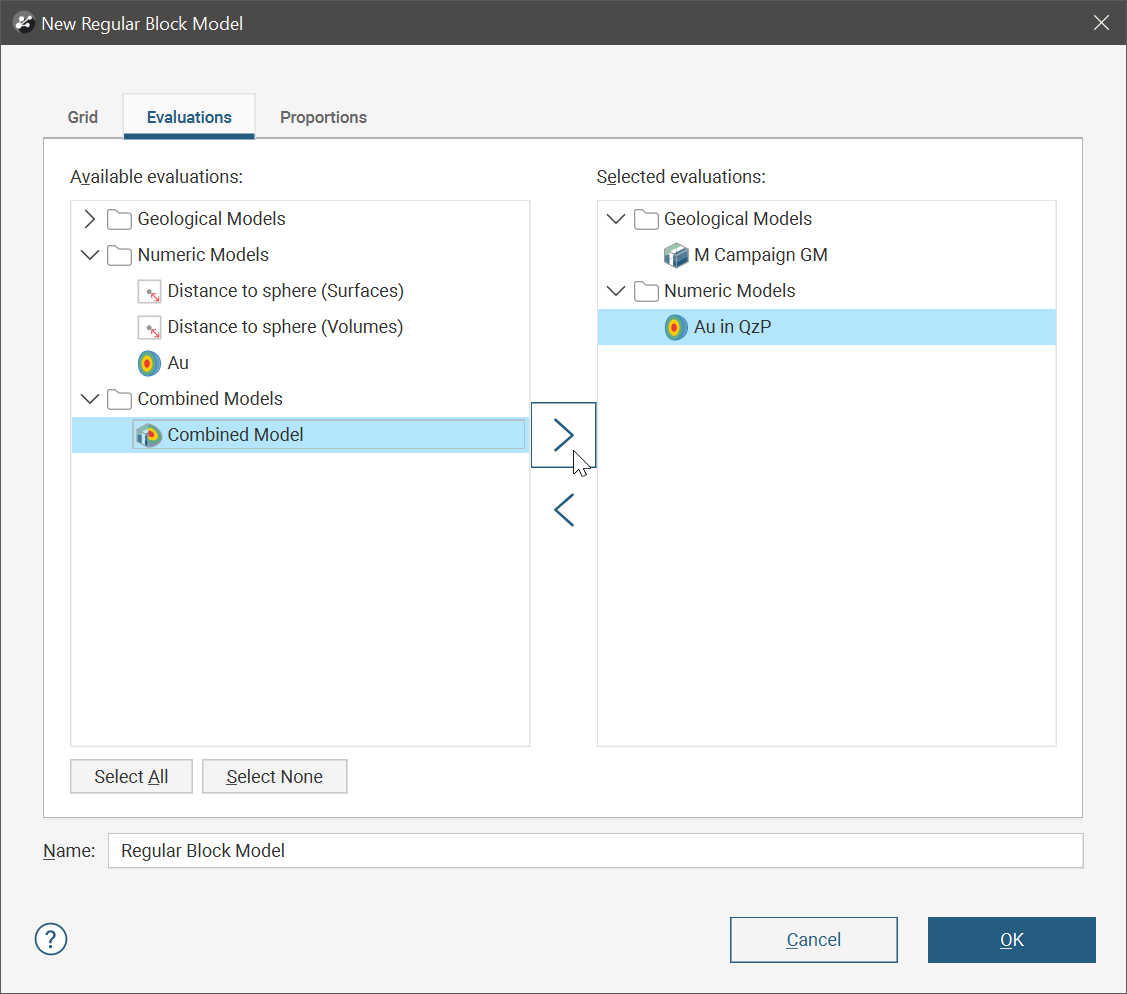
Selecting Evaluations
You can also evaluate the block model against geological models, interpolants and distance functions in the project. To do this, click on the Evaluations tab. All objects available in the project will be displayed. Move the models you wish to use into the Selected evaluations list.
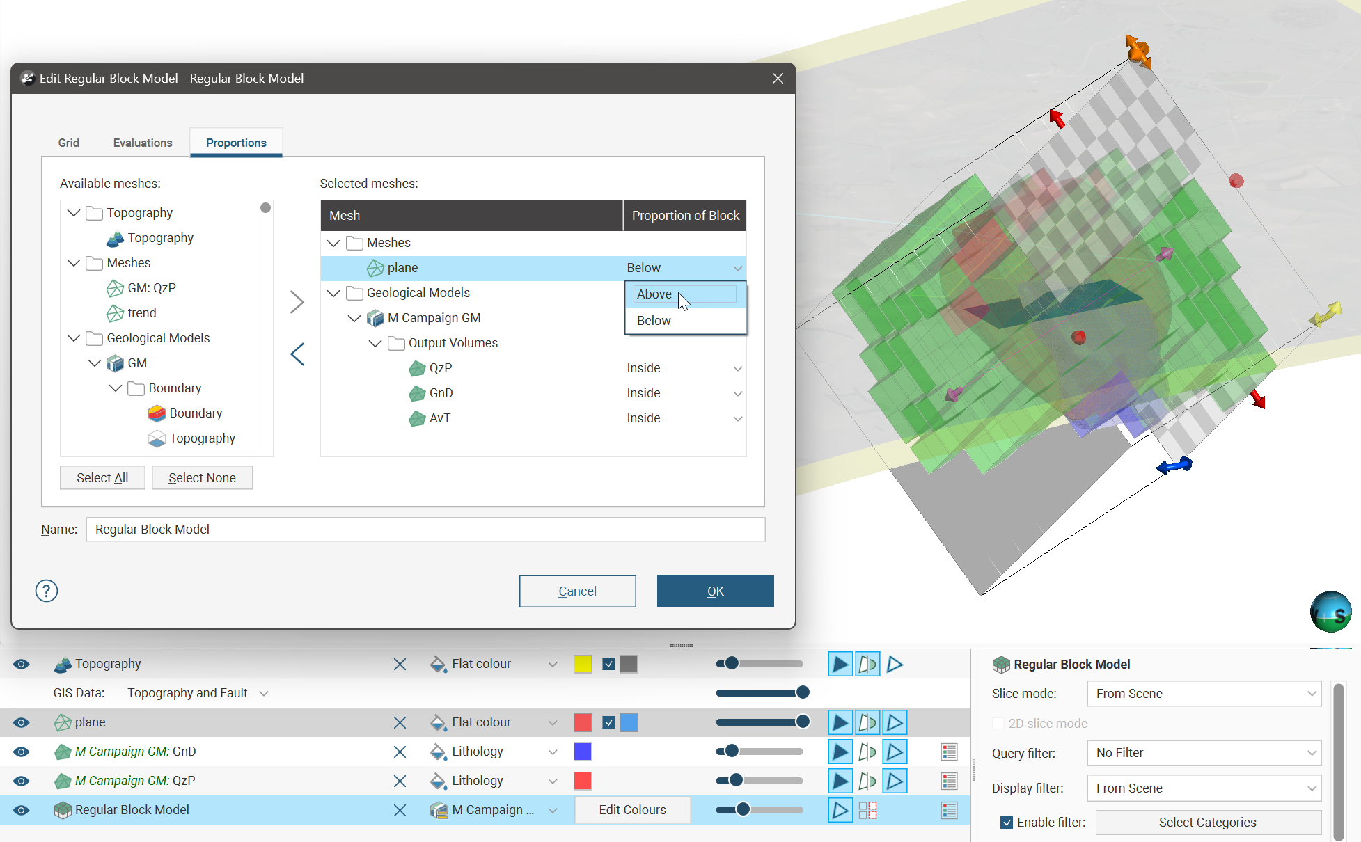
Selecting Meshes for Calculating Proportions
Click the Proportions tab and select meshes from the list of Available meshes, moving them to the Selected meshes list. The Proportions of Block column specifies the region of interest relative to the selected mesh. Closed meshes have options of Inside and Outside, and open meshes have the options of Above and Below.
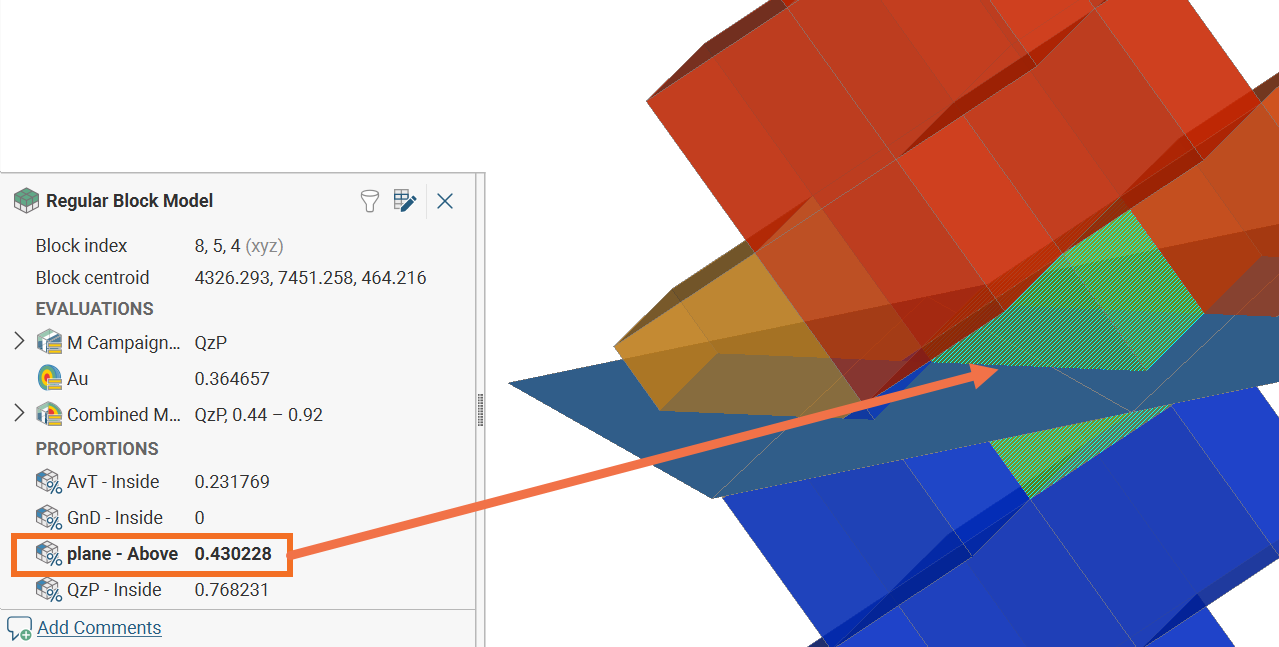
Each block will have a proportion calculated according to the ratio of each block relative to the Proportions of Block options for each surface. In the following example, a little less than half of the selected block is above the mesh called ‘plane’, and the exact proportion has been calculated as 0.430228. The same block has a proportion of 0.768231, or just under 77%, inside a mesh called ‘QzP’ (not shown).
When determining the proportion of a block above or below a selected mesh, if any part of a block falls outside a vertical projection of the outer edges of the surface, the proportion will be set to the special value Outside. Only blocks that are entirely within the vertical projection of the surface edge will be assigned a proportion value.
Non-manifold and self-intersecting meshes cannot be used for calculating proportions. Additionally, it is not possible to calculate the proportions above or below an open surface if there are overhangs and overlaps in the mesh.
Exporting Regular Block Models
Regular block models can be exported in CSV, Datamine, Surpac and Geosoft Voxel formats. See: