
Multiple Deviation Planner
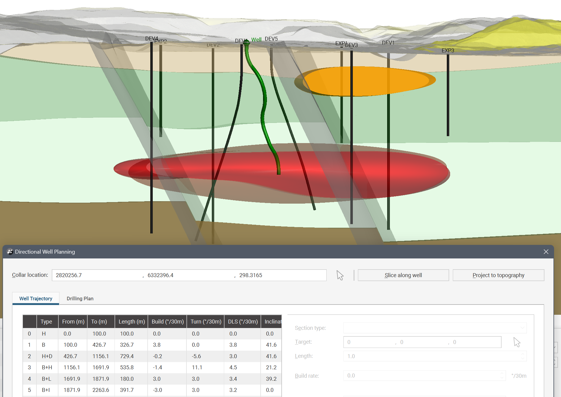
Directional wells are used to reach targets that might be otherwise impossible to reach with a vertical well or to reach a spread of targets from a single drilling area. In Leapfrog Energy, you can define a directional well by adding different sections to the well path, then changing their Section type and parameters. The example illustrated here is not realistic, but it does demonstrate the flexibility of the directional drilling tool:
The final planned well can be exported as interval tables, as points or as a drilling plan. You can also import a drilling plan.
This topic describes how to use the directional drilling planner. It is divided into:
- Adding a Directional Well
- Viewing Drilling Prognoses
- Exporting Planned Wells
- Importing Planned Wells
Adding a Directional Well
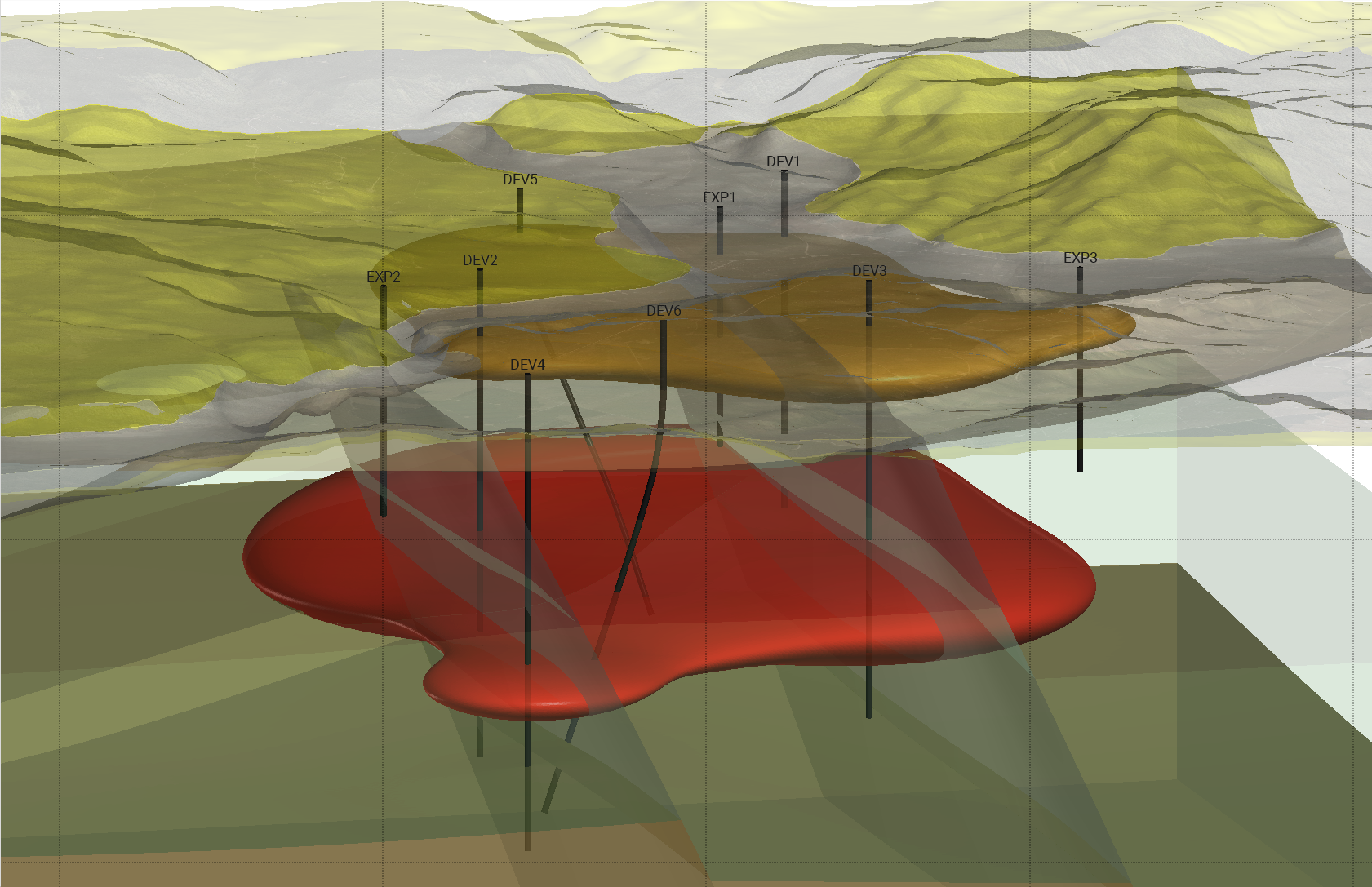
To plan a directional well, first add items to the scene that will assist you in locating a suitable path for the well. You may want to add topography, a geological model, faulting and existing wells to the scene.
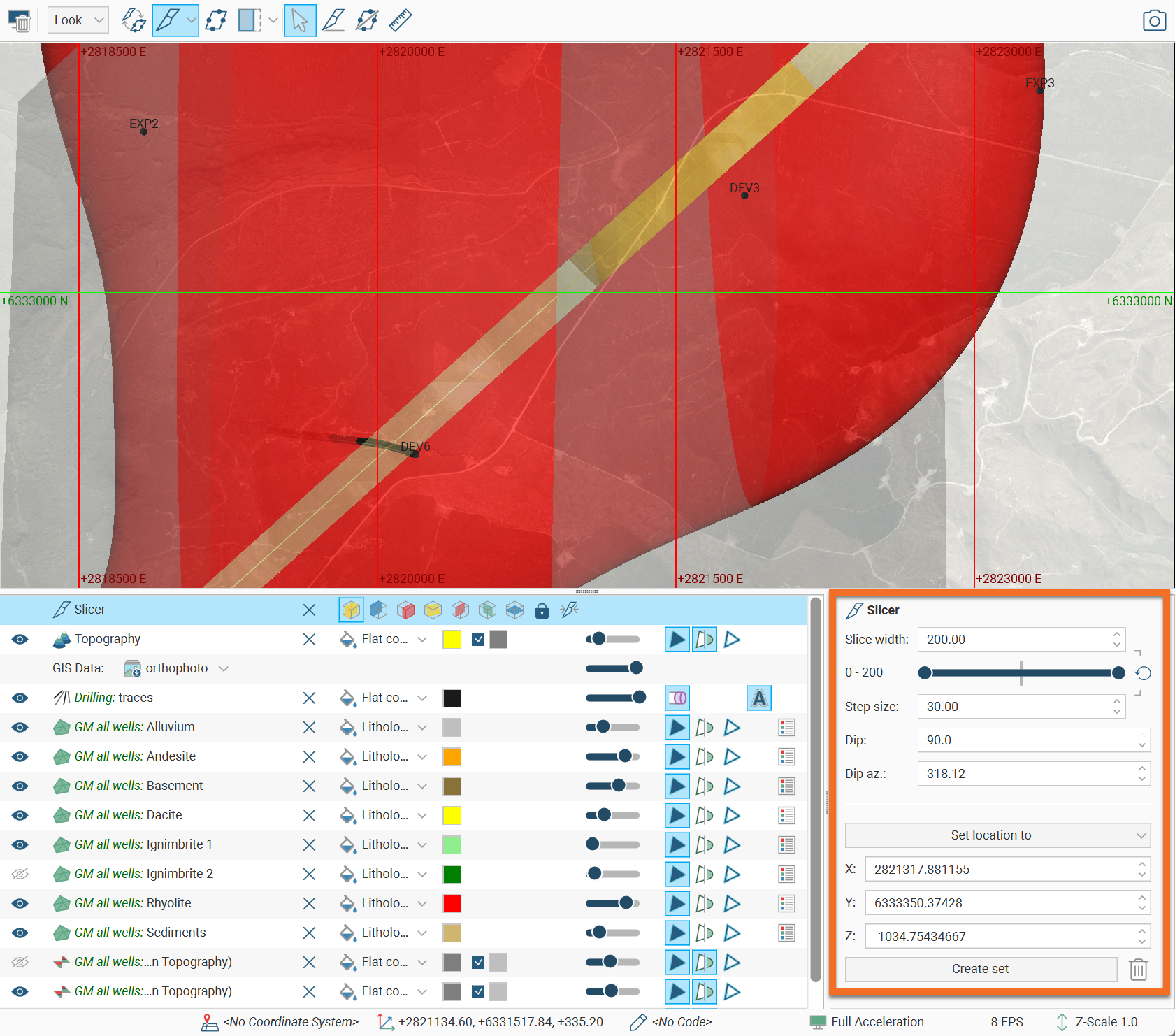
Slice the scene roughly where you want the well to be drilled.
Adjust the slice orientation using the Dip and Dip az. controls in the slicer’s properties panel. You can also use the X, Y and Z fields to adjust the position:
The slicer’s Dip az. direction can be used as the reference azimuth direction for the planned well. When clicking on the scene to set a drilling target, choose Remove front or Remove back slicer display options to click directly on the slicer plane, being careful to hide other objects that might be in the foreground that would prevent clicking directly on the slicer plane.
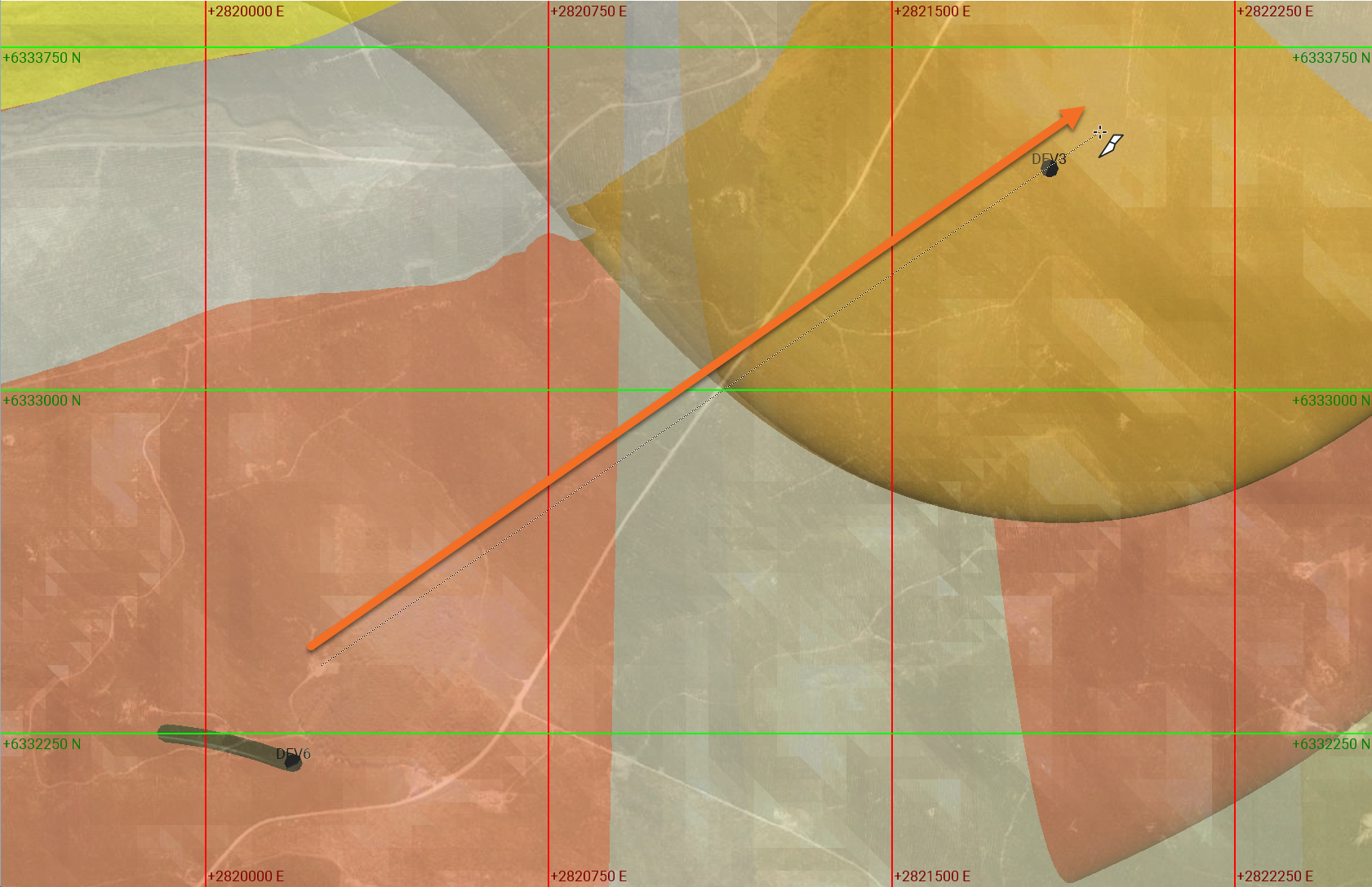
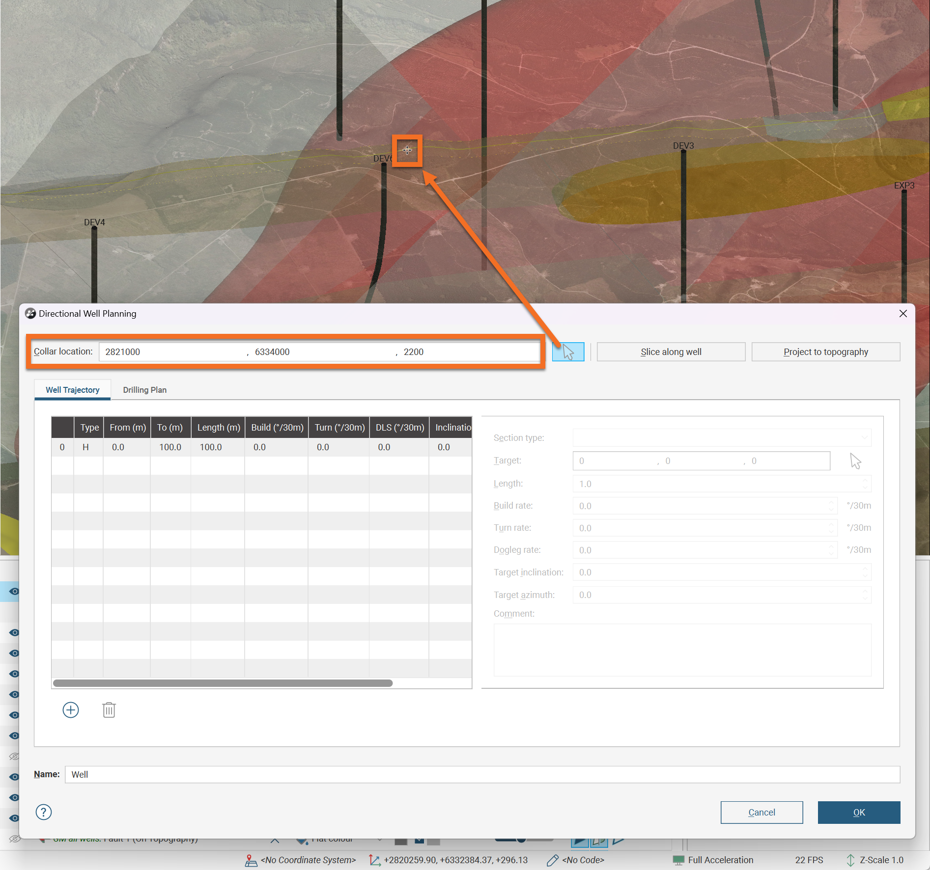
Right-click on the Planned Wells folder and select Plan Directional Well. The Directional Well Planning window will appear. It shows a default section has already been added to the plan, but the well has not yet been located. To set the location of the top of the well, click the Collar location button (![]() ) next to the Slice along well button, then click in the scene where the top of the well should be located. The Collar location information in the Directional Well Planning window will be updated. In this example, the top of the well is being placed where the aerial imagery projected onto the topography shows an existing cleared area with vehicle access.
) next to the Slice along well button, then click in the scene where the top of the well should be located. The Collar location information in the Directional Well Planning window will be updated. In this example, the top of the well is being placed where the aerial imagery projected onto the topography shows an existing cleared area with vehicle access.
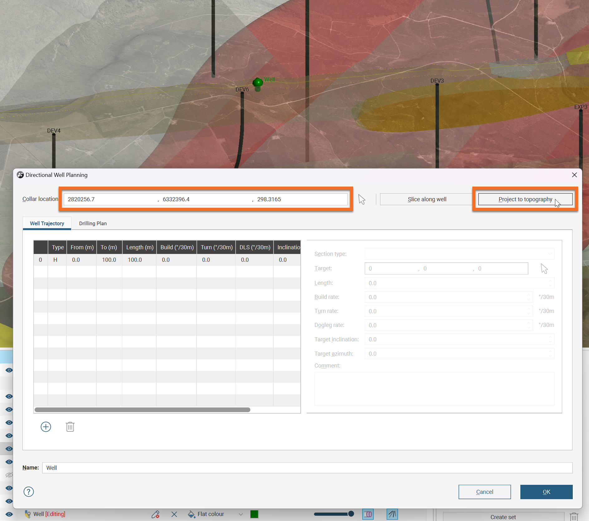
Click the Project to topography button to force the top of the well to sit on the topography. Notice that the Collar location values have been updated after this button was clicked:
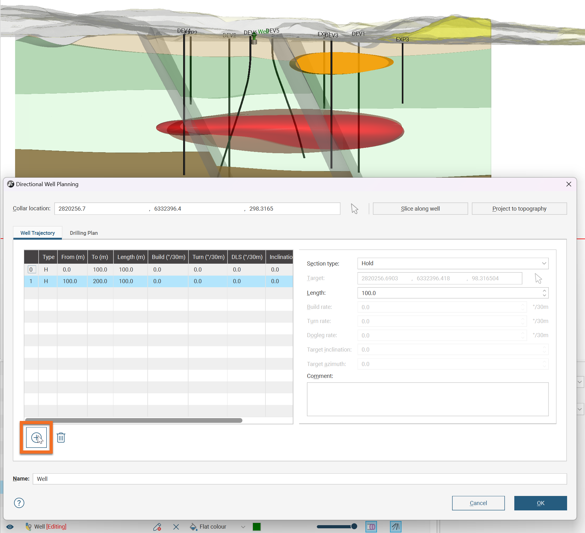
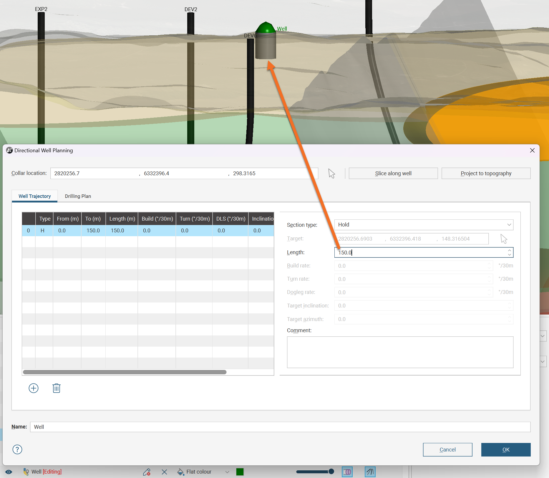
The path of the well is defined by adding different sections, then changing their Section type and parameters. By default, the first section of the planned directional well is a Hold type section, 100m long.
Click the Add button to add another section to the planned directional well. By default, the previous section will be duplicated, and you change the section type and other parameters as needed.
Each Section type is described below:
- Hold Sections
- Build Sections
- Hold + Drop Sections
- Build + Hold Sections
- Build to Length Sections
- Build to Inclination Sections
Note that curved sections are described using the industry standard ‘degrees per 30m’. For those using imperial measures, the curved sections are considered in terms of degrees per 30ft.
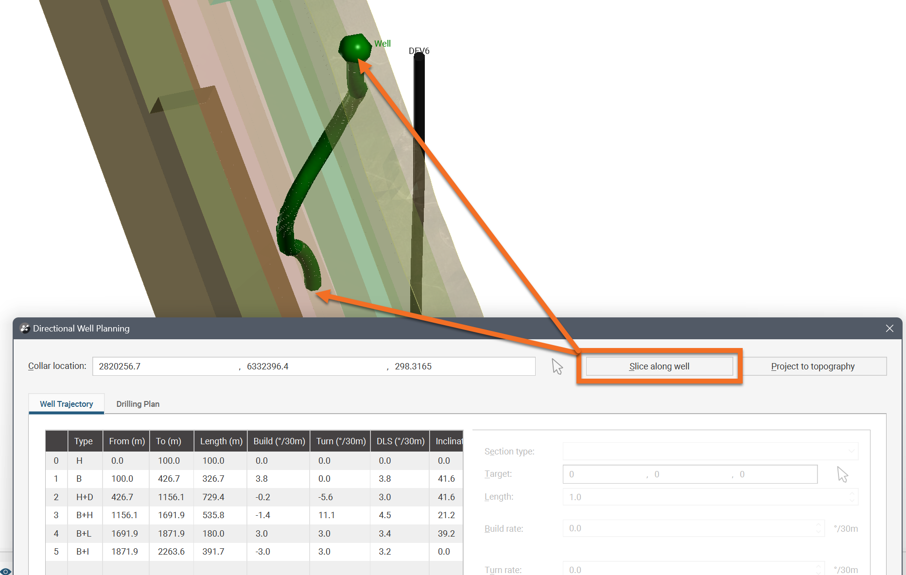
Once you have defined the well, use the Slice along well button to create a slice that intersects the collar and the end of the well. This is most useful once your well is defined. To get control over the reference azimuth for the build curves in your well, set the orientation of the slicer directly when creating the planned directional well. Then when you click on the scene to set a drilling target, choose Remove front or Remove back slicer display options to click directly on the slicer plane, being careful to hide other objects that might be in the foreground that would prevent clicking directly on the slicer plane.
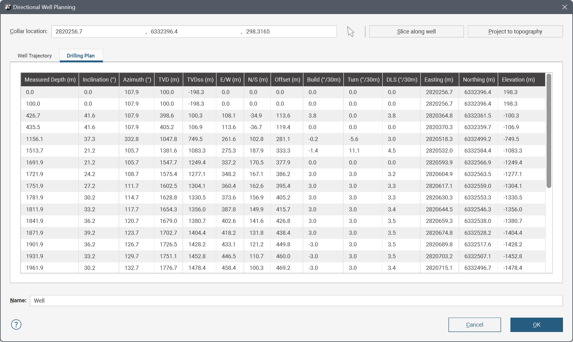
Select the Drilling plan tab to see the planned directional well in terms of a drilling plan instead of a trajectory.
Hold Sections
A Hold section continues the well at the current Target inclination and Target azimuth for the specified Length. At the start of the well, the assumed Target inclination and Target azimuth are 0, to define an initial vertical section. You can change the Length for a Hold section, but no other parameters can be adjusted.
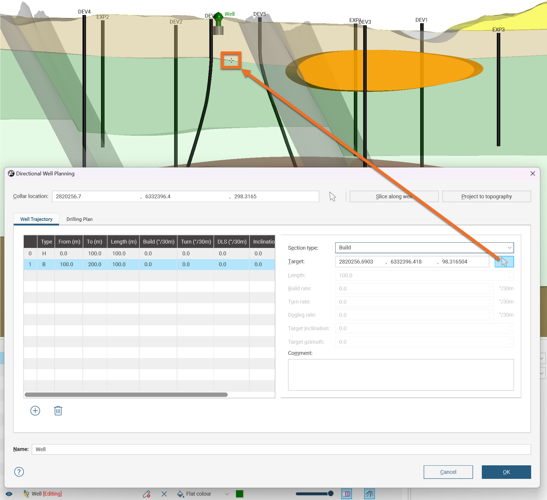
Build Sections
A Build section is a curved section, changing the direction of the well in a single simple curve. The curve is defined by two points: the current end of the planned well and a specified Target location. To create the curve joining them, the minimum curvature method is used to define the shape of the curve. The Target location can be specified using X, Y and Z coordinates, or you can click the Target select button and click in the scene to set the target at a specific point on the slicer plane.
If you are looking down the plane of the slicer in the scene, you will not be able to click in the scene anywhere that will let you build towards the slicer plane. Rotate the scene so you can click on the slicer plane. To do this, press the L key to quickly orient the camera orthogonally towards the slicer. If the slicer does not cut across a part of the scene you want to build toward, reorient and reposition the slicer.
Note that clicking in the scene may not select a point on the slicer plane if another object is in the way. This includes the sides of the slice when the slicer is using the Thick slice display option. In this case, the selected point will be on the side of the thick slice, not on the slicer plane.
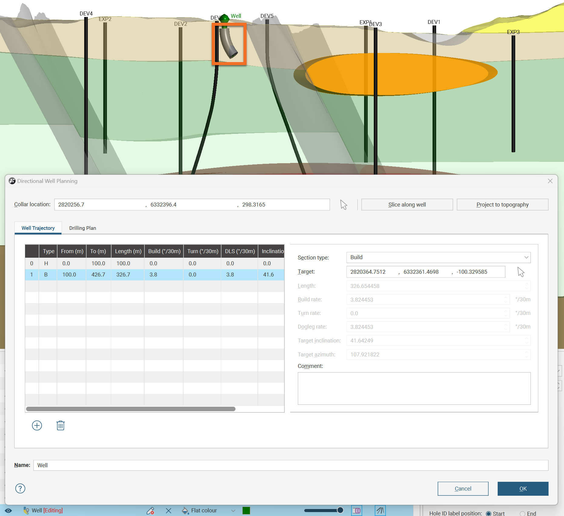
A single Dogleg rate will be calculated to drill from the current end point in the current direction, to the specified location. This will be expressed as a fixed Build rate and Turn rate and the resultant inclination and azimuth of the new end of the well will be shown as the Target inclination and Target azimuth.
The new section will be drawn and highlighted in the scene as shown.
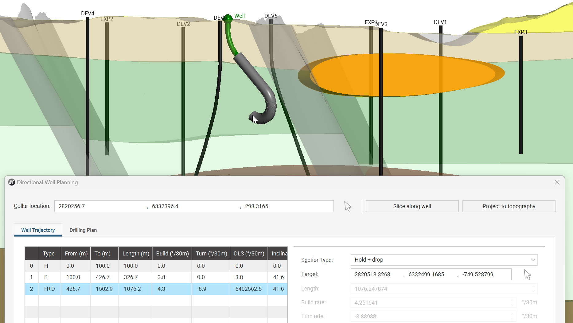
Hold + Drop Sections
A Hold + drop section continues the planned well in the current inclination and azimuth for a certain distance, then begins to curve at a constant given rate. As for a Build section, you need to select a Target location, either using the X, Y and Z coordinates, or you can click the Target select button and click in the scene to set the target at a specific point on the slicer plane.
If you are looking down the plane of the slicer in the scene, you will not be able to click in the scene anywhere that will let you build towards the slicer plane. Rotate the scene so you can click on the slicer plane. To do this, press the L key to quickly orient the camera orthogonally towards the slicer. If the slicer does not cut across a part of the scene you want to build toward, reorient and reposition the slicer.
Note that clicking in the scene may not select a point on the slicer plane if another object is in the way. This includes the sides of the slice when the slicer is using the Thick slice display option. In this case, the selected point will be on the side of the thick slice, not on the slicer plane.
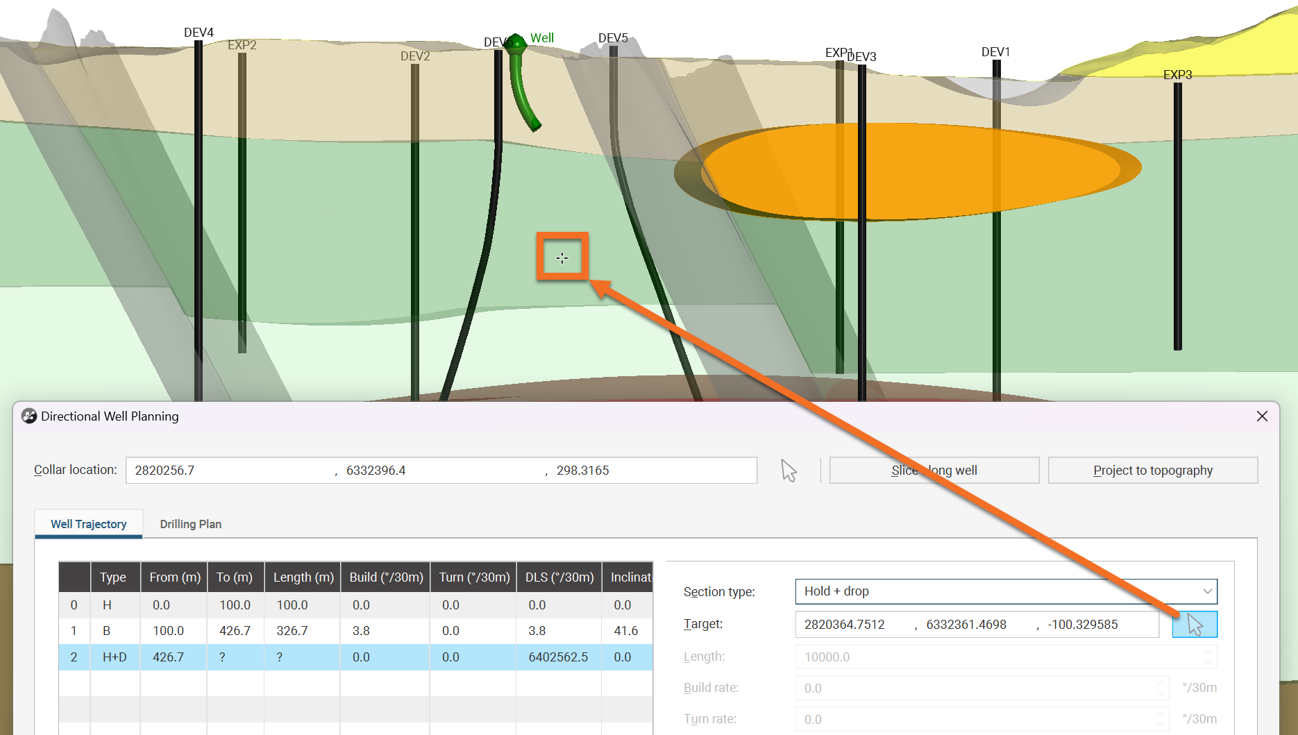
The section will be drawn using a default Dogleg rate that you will need to change.
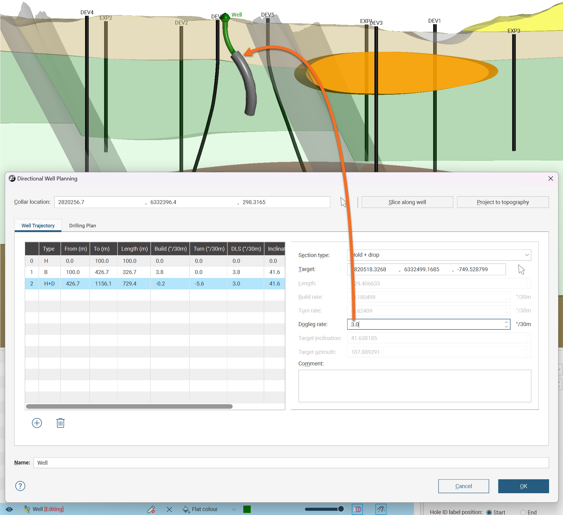
The Dogleg rate you specify is the constant rate of change in the curved section, and making the Dogleg rate tighter will increase the straight Length needed to start the section before the curve starts to turn toward the Target location.
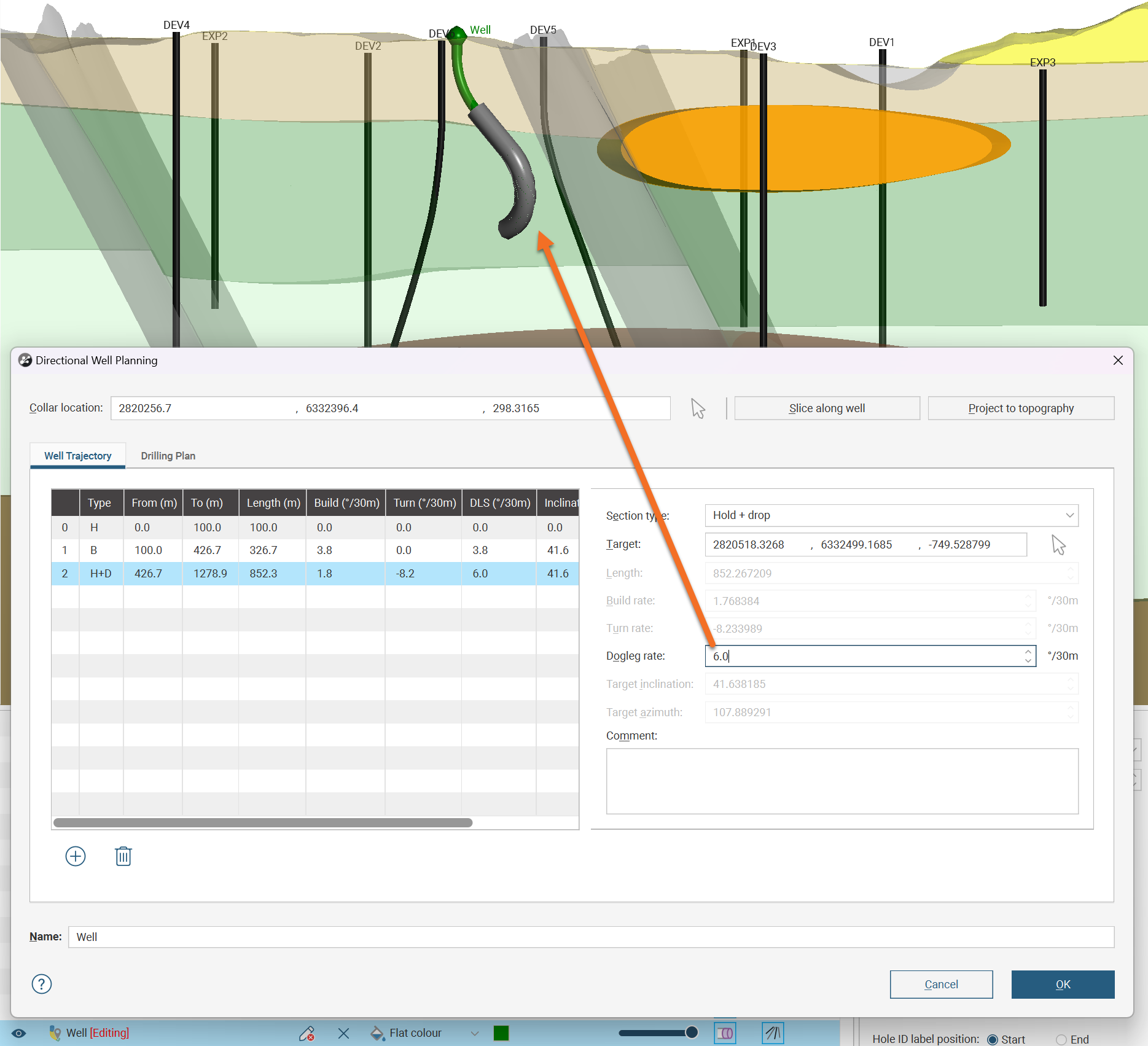
You can reduce the Dogleg rate only to the point that the straight section vanishes and a simple curve extends from the start to the end of the Hold + Drop section.
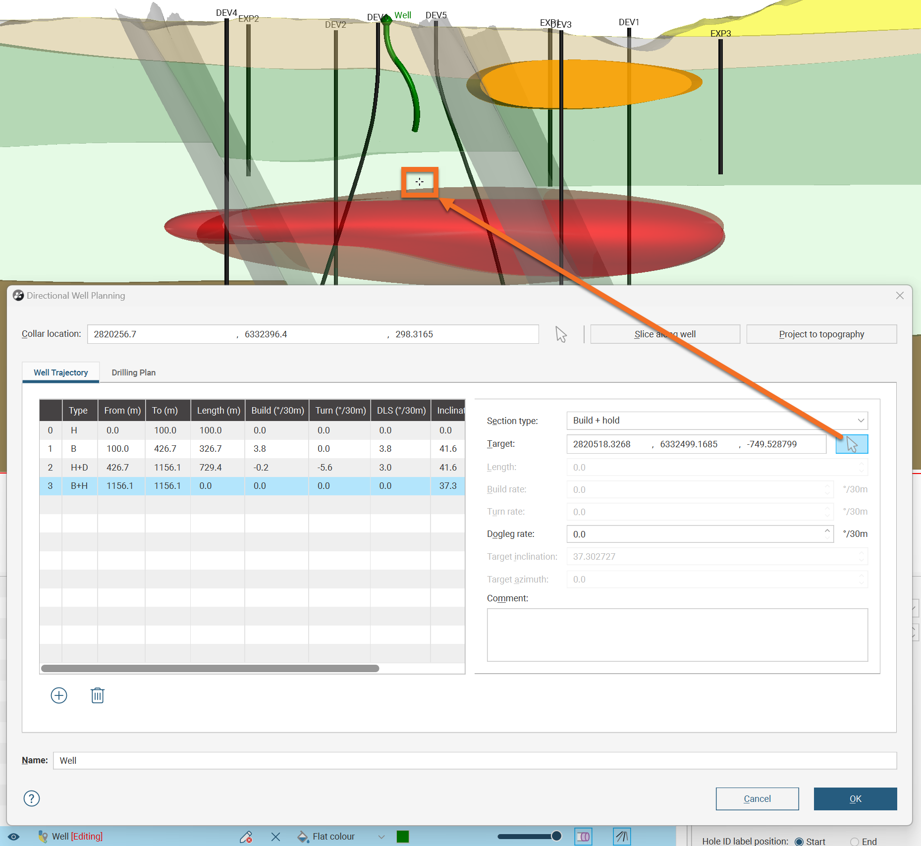
Build + Hold Sections
A Build + hold section is similar to a Hold + drop section, but with the straight and curved parts the other way around. A Build + hold section also requires the selection of a Target location. Use the X, Y and Z coordinates, or click the Target select button and click in the scene to set the target at a specific point on the slicer plane.
If you are looking down the plane of the slicer in the scene, you will not be able to click in the scene anywhere that will let you build towards the slicer plane. Rotate the scene so you can click on the slicer plane. To do this, press the L key to quickly orient the camera orthogonally towards the slicer. If the slicer does not cut across a part of the scene you want to build toward, reorient and reposition the slicer.
Note that clicking in the scene may not select a point on the slicer plane if another object is in the way. This includes the sides of the slice when the slicer is using the Thick slice display option. In this case, the selected point will be on the side of the thick slice, not on the slicer plane.
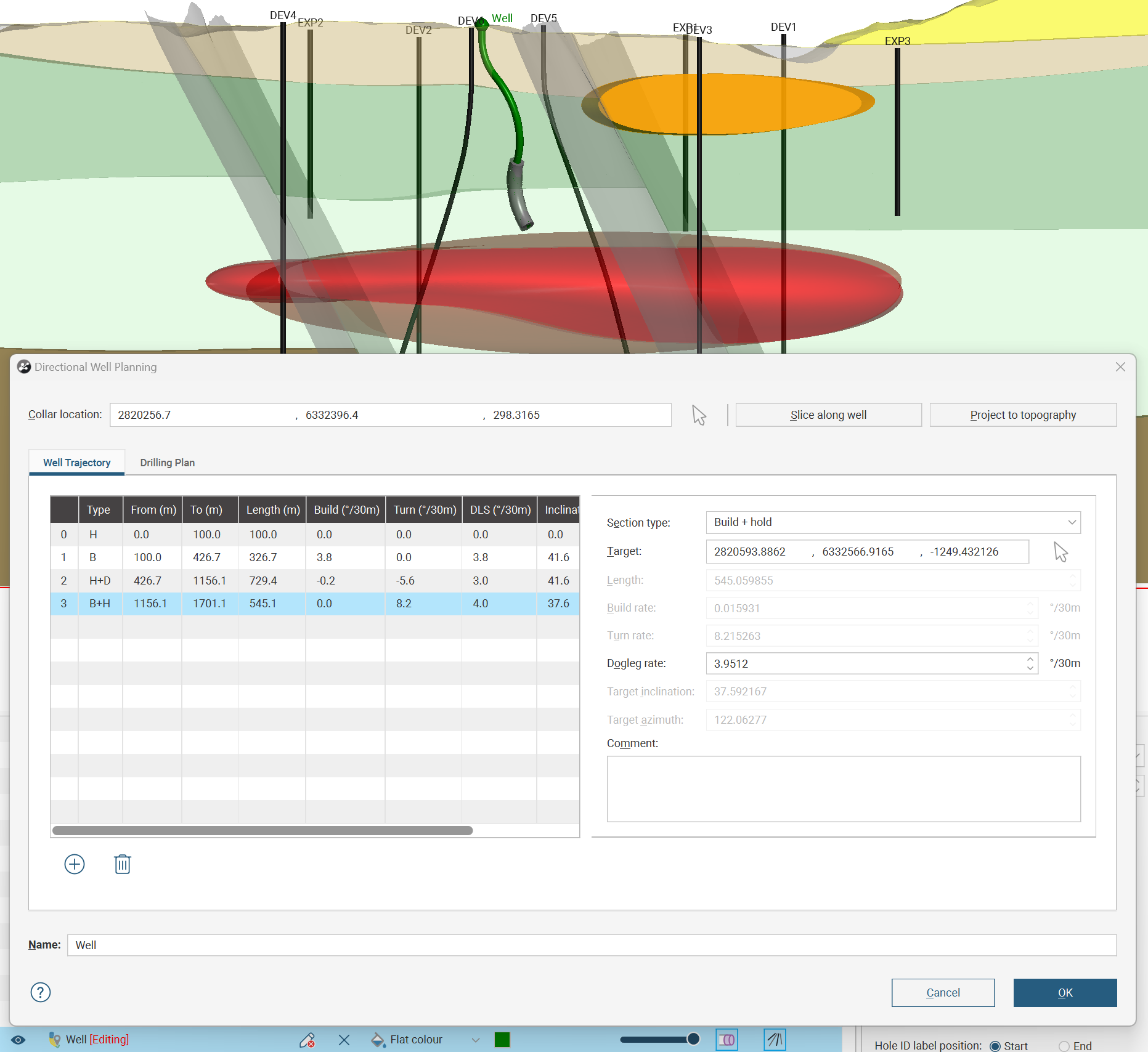
The section will be drawn using a default Dogleg rate that provides a constant curve from the start of the section to the end of the section.
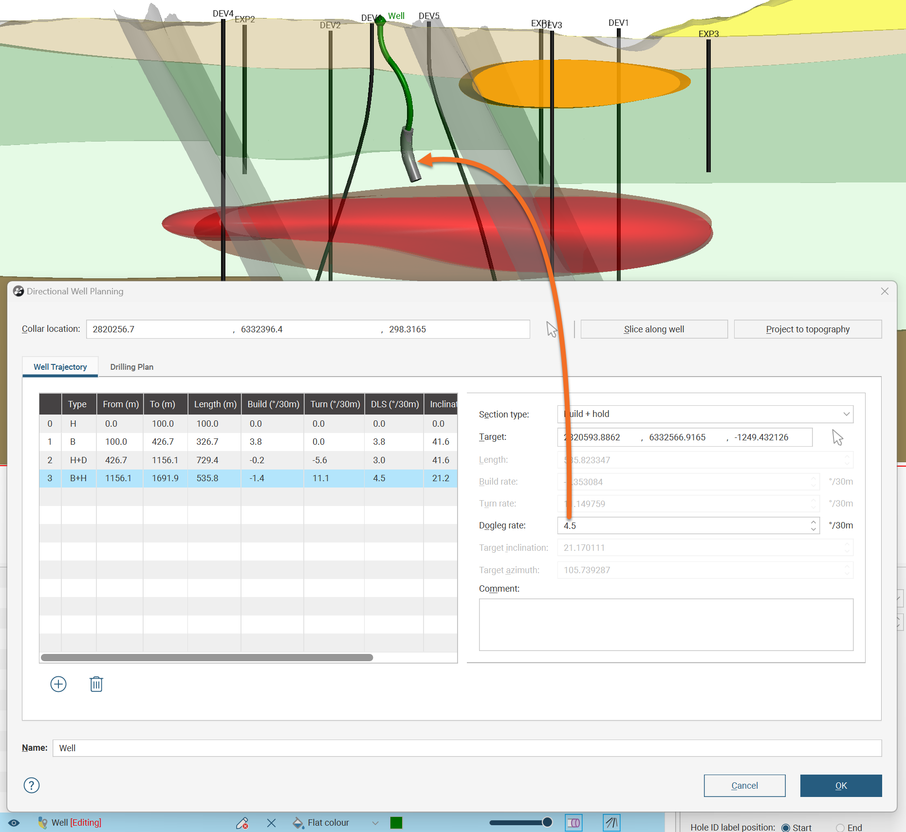
You can change the Dogleg rate, the constant rate of change in the curved section, and making the Dogleg rate tighter will increase the straight Length needed to finish the section after the curve ends to extend the well out to the Target location. You can reduce the Dogleg rate only to the point that the straight section vanishes and a simple curve extends from the start to the end of the Build + Hold section.
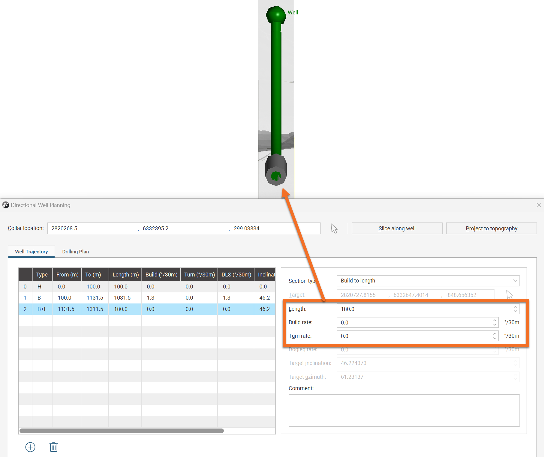
Build to Length Sections
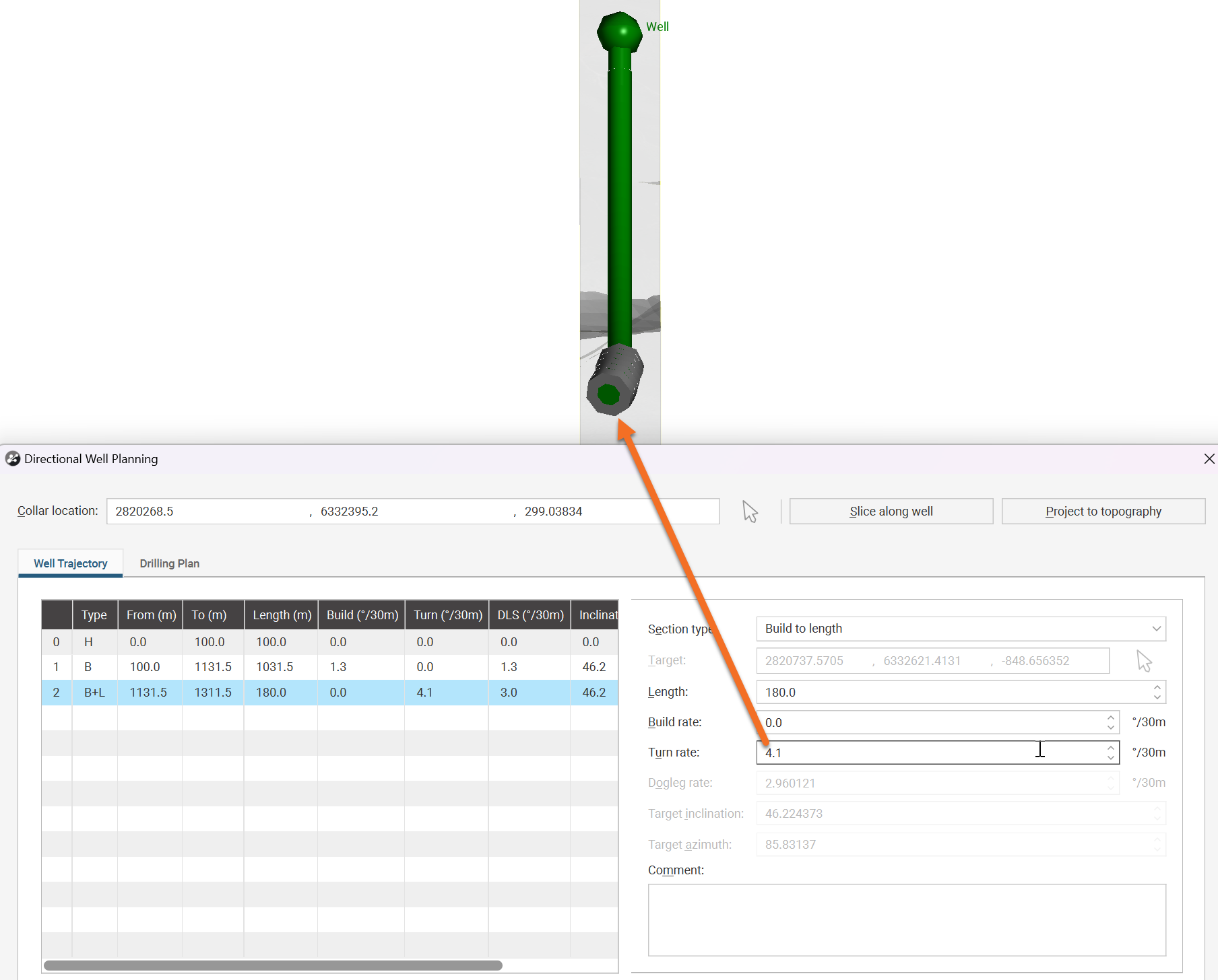
A Build to length section creates a section to a specified length, curved at a specified Build rate and Turn rate. If no Build rate or Turn rate are specified, the section will be straight, like a Hold section. To see the effect of these options more clearly, here we look upwards from the end of the planned directional well a Built to length section has been added onto. Note that a 180m straight section is pointing almost straight at us.
Specifying a Turn rate will define a curve off to one side, changing the azimuth direction of the well.
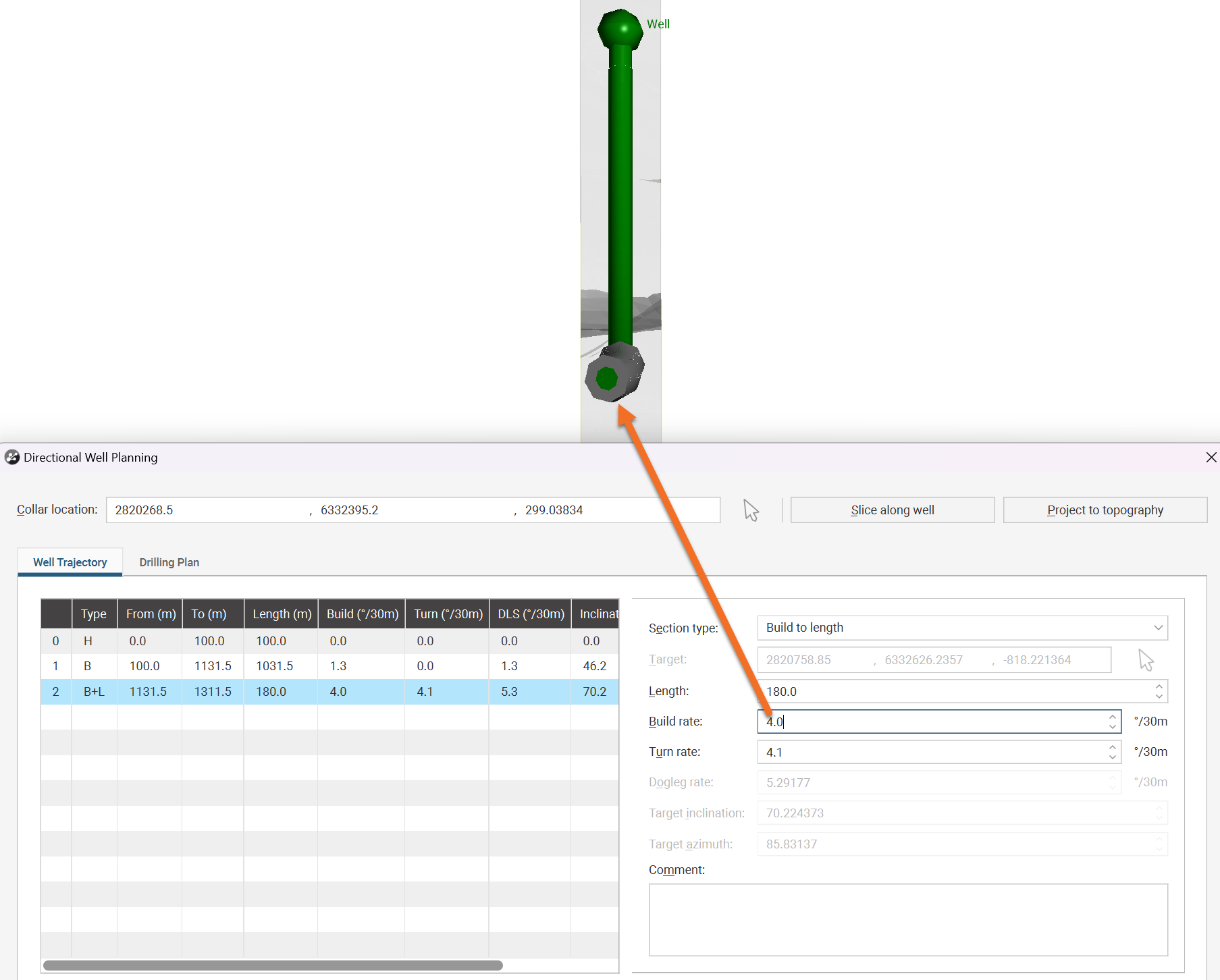
Specifying a Build rate will curve the well without changing the azimuth, although if it is combined with a Turn rate there will be a net change in azimuth direction. Note the combined Dogleg rate is calculated and shown so you can check you are not exceeding the maximum rate the drilling equipment supports.
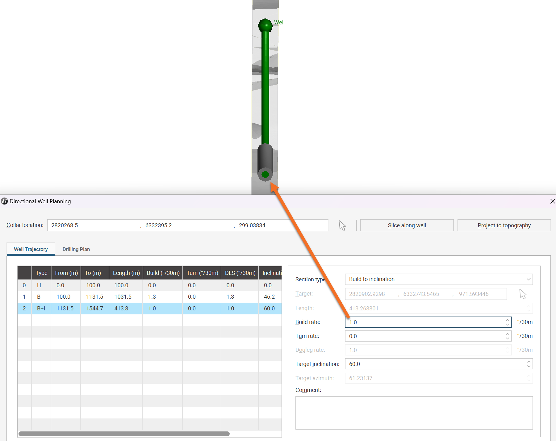
Build to Inclination Sections
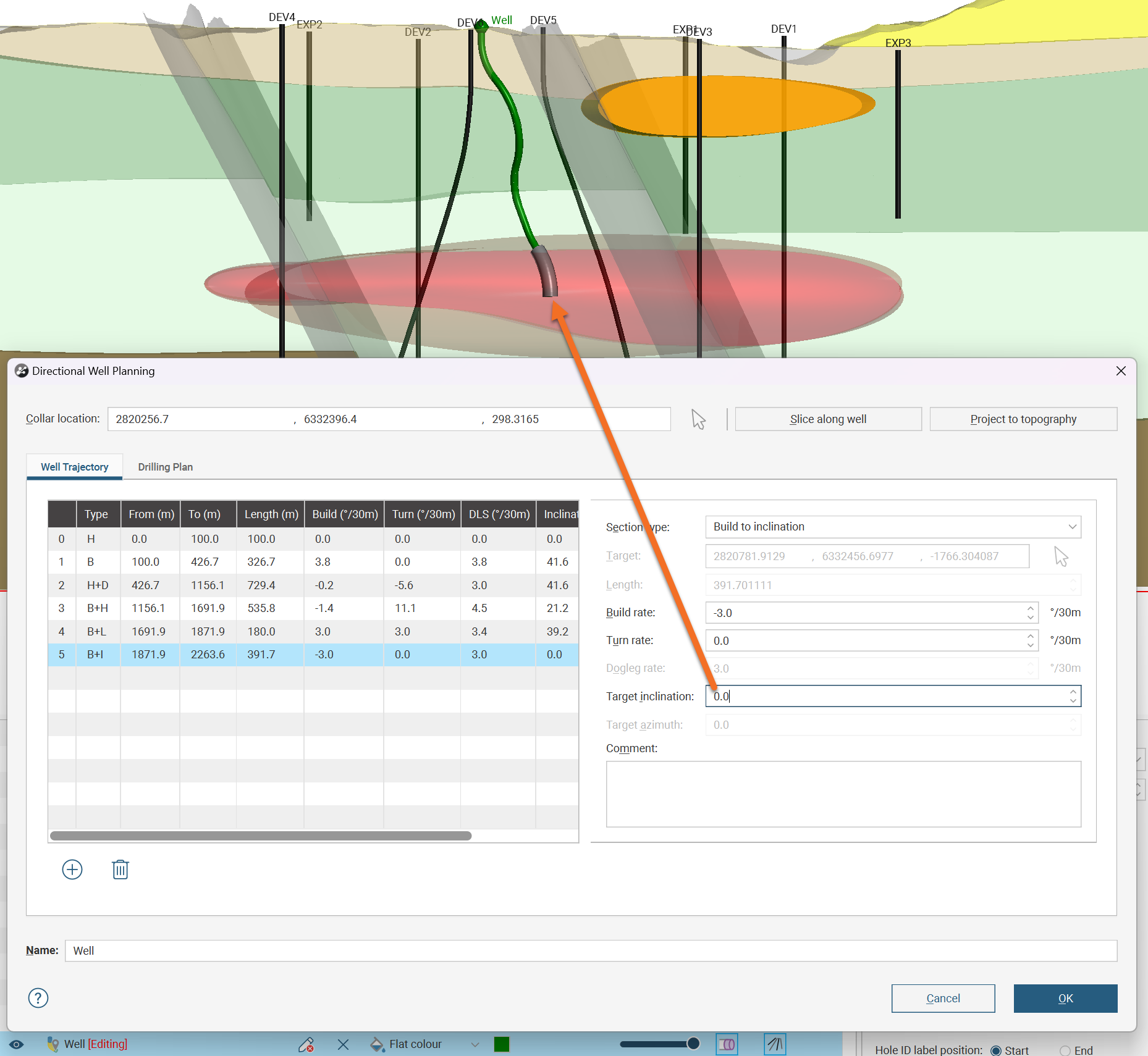
A Build to inclination section creates a curve that terminates in a desired inclination angle, without regard for the well length required to achieve this result. You need to specify a Build rate and Turn rate to use to turn the well towards the desired angle, but until you change the Target inclination angle no new section will appear in the scene. Similarly, you can set a Target inclination, but no new section will appear until you specify a Build rate or Turn rate. You might use the Build to inclination option to ensure that a well finishes with a lateral cut such as this level 90° inclination.

More often, Build to inclination might be used to finish the well vertically, with the Target inclination set to 0°:
To visualise the effect of the Build to inclination option, we again will look at the end of the well we are defining. Here the section has been added and the Target inclination has been set to 0°, but no highlighted section is shown in the scene as we have not yet specified how to curve the well towards the Target inclination.
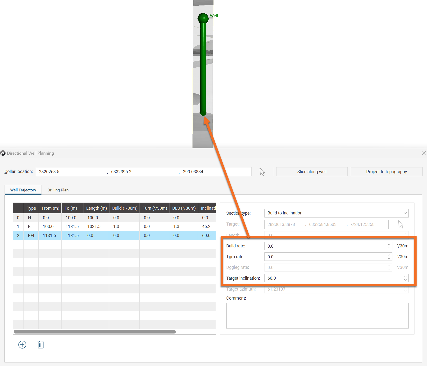
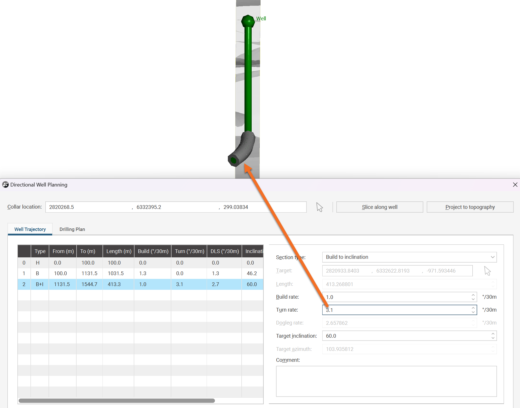
As soon as we specify a Build rate, the well can curve towards the Target inclination.
You can change the Target azimuth angle by adjusting the Turn rate to get the well terminating at precisely the angle you want.
Viewing Drilling Prognoses
Directional wells can be evaluated against any model in the project. Right-click a planned well in the project tree and select Evaluations, then move models to evaluate from the Available list to the Selected list.
To view drilling prognoses for a planned well, right-click on it and select Drilling Prognoses. The Drilling Prognoses window will appear:
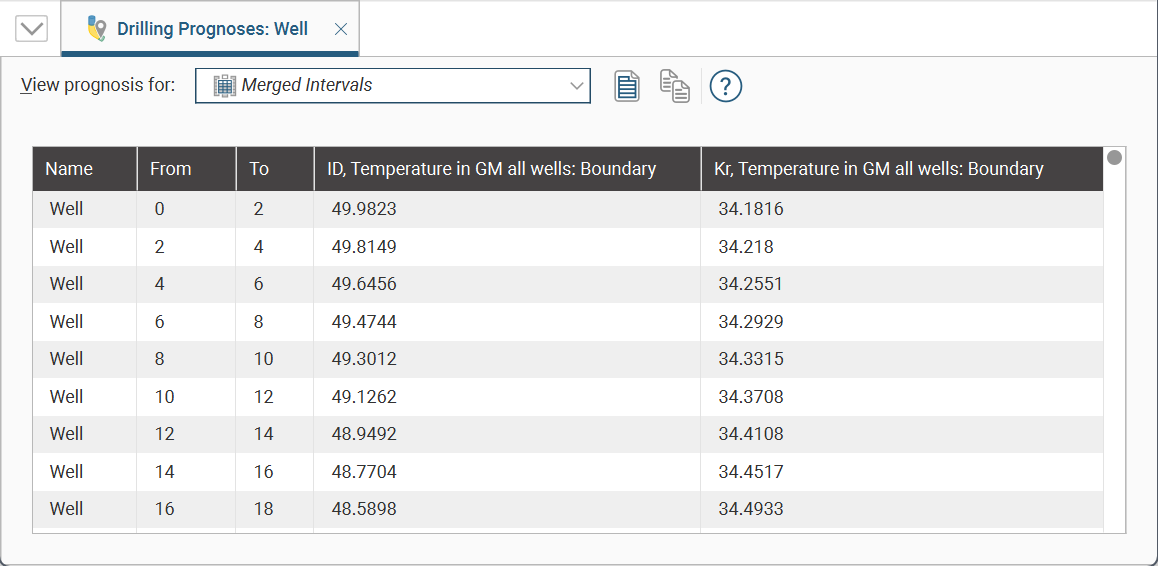
The dropdown list contains all evaluations on the well, along with a Merged Intervals option that combines the information from all evaluations. You can copy the information displayed to your computer’s clipboard by selecting rows, then clicking the Copy button (![]() ). The information in the selected rows will be copied as tab delimited text, which can be copied into a spreadsheet application such as Excel.
). The information in the selected rows will be copied as tab delimited text, which can be copied into a spreadsheet application such as Excel.
Exporting Planned Wells
There are four ways to export information from planned directional wells:
Exporting as Interval Tables
A planned well can be exported as interval tables in *.csv format. To do this, right-click on the well and select Export as Interval Tables. In the Export Directional Well Tables window, the files that will be created are listed, one each for the collar and survey table and one for the evaluations:
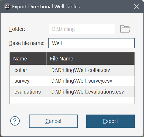
Change the Base file name, if required, choose a folder in which to save the files, then click Export to save the files.
Exporting as Points
A planned well can be exported as a points table in *.csv format. The file will contain X, Y and Z values, along with measured depth and true vertical depth columns. Any evaluations on the well can also be included.
To export a planned well as points, right-click on the well and select Export as Points. In the window that appears, select where you wish to save the file, enter a file name and then click Save. Next you will be prompted to select which evaluations to include:
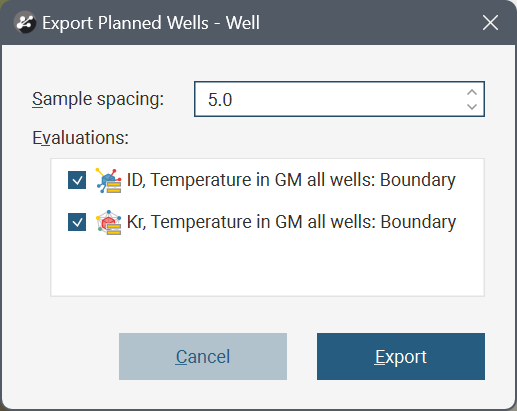
Set the Sample spacing and the evaluations you require, then click Export.
Exporting as a Polyline
A planned well can be exported as a polyline the following formats:
- Leapfrog Polylines (*.lfpl)
- Leapfrog Mining Polylines (*.csv)
- Drawing Interchange Polylines Files (*.dxf)
- Surpac String Polyline Files (*.str)
- Gocad Polylines Files (*.pl *.ts)
- MineSight Polylines Files (*.srg)
- Datamine Polylines Files (*.asc)
- Micromine Polylines Files (*.str *.asc)
- AutoCAD Drawing Files (2013/LT2013) (*.dwg)
- Bentley Drawing Files (v8) (*.dgn)
To export a planned well as a polyline, right-click on the well and select Export as Polyline. In the window that appears, select where you wish to save the file, enter a file name, select the file type from the Save as type options, and then click Save.
Exporting a Drilling Plan
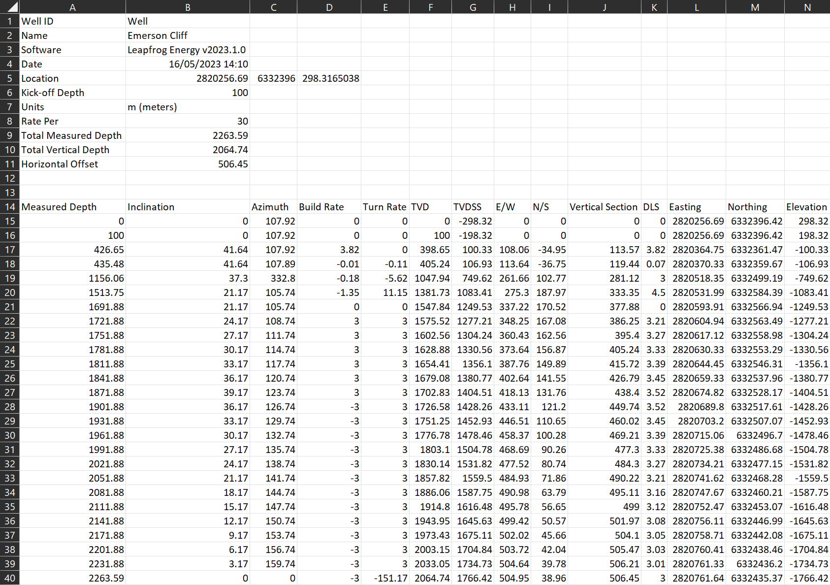
A drilling plan can be exported for a planned directional well.
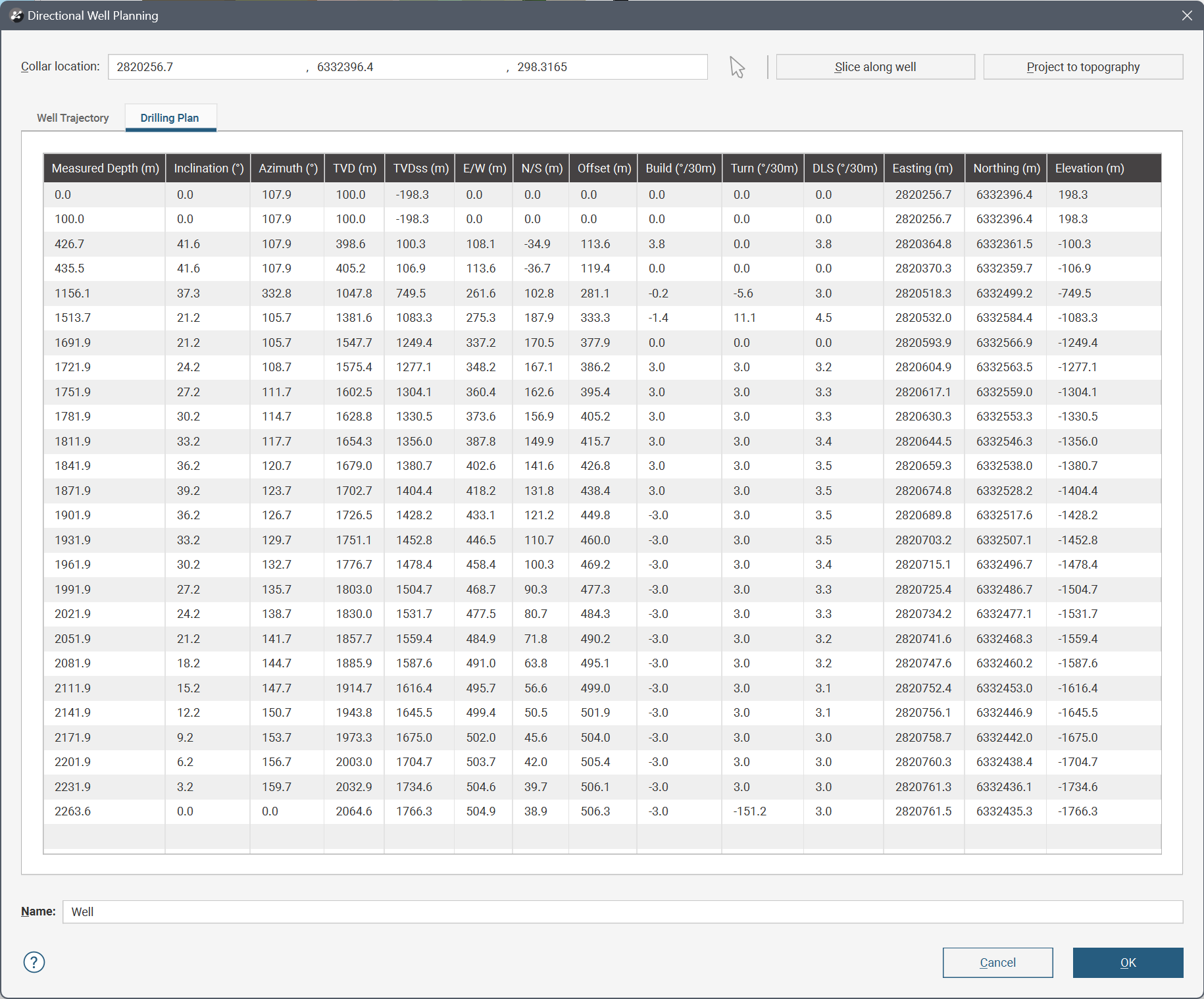
To preview the information that will be included in the drilling plan, double-click on the planned directional well in the project tree and then click on the Drilling Plan tab:
To export the drilling plan, right-click on the well and select Export Drilling Plan. In the window that appears, select where you wish to save the file, enter a file name and then click Save. The file will then be saved.
Importing Planned Wells
Leapfrog Energy imports planned directional wells from files in *.csv format.
To import a drilling plan, right-click on the Planned Wells folder and select Import Directional Drilling Plan. Select the file and click Open. If there are no conflicts, the planned well will be added to the Planned Wells folder and will be opened in the Directional Well Planning window.