
Reservoir Simulation Models
Leapfrog Energy reservoir simulation modelling capability provides a sub-surface workflow for creating and updating flow simulation models based on geological modelling, supporting ECLIPSE and CMP simulators as targets for the models produced.
The rest of this topic describes working with reservoir models in Leapfrog Energy. It is divided into:
- Creating a New Reservoir Simulation Model
- Adjusting the Boundary
- Editing Pillar Spacings
- Adding Control Lines
- Editing the Grid Layers
- Reservoir Simulation Evaluations
- Setting Active and Pinchout Masks
- Exporting a Reservoir Simulation Model
Creating a New Reservoir Simulation Model
To create a new reservoir simulation model, you must first have at least one geological model defined in the project. Once this has been defined, add the geological model to the scene. Right-click on the Flow Models folder and select Reservoir Simulation > New Model. The New Reservoir Simulation Model window will be displayed, together with controls in the scene that will help you to set the grid extents:
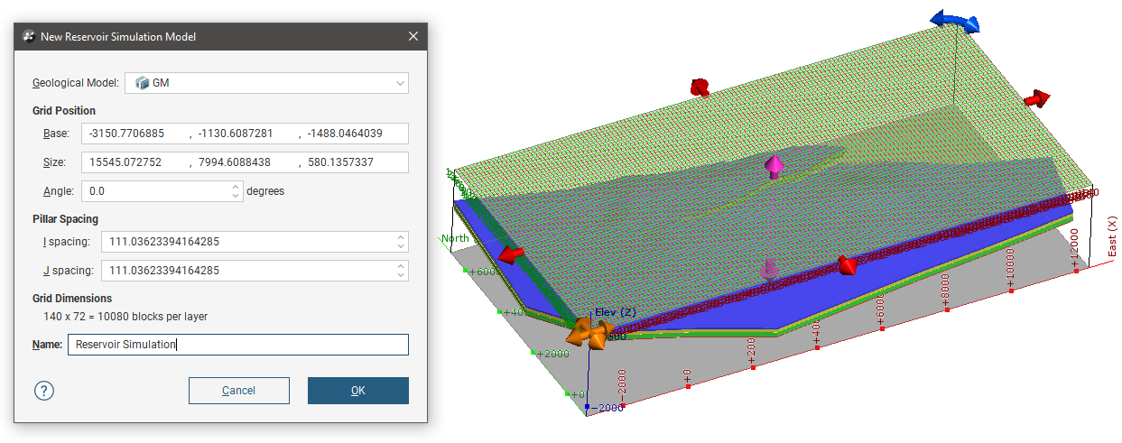
The new reservoir simulation model will be based on the geological model selected in the Geological Model dropdown. A grid will be created by default to encompass the entire geological model. You can alter the Grid Position by amending the X, Y and Z parameters for the Base point and the grid Size dimensions. The Pillar Spacing can be altered by changing the I spacing and J spacing values. Under Grid Dimensions, the number of pillars in the reservoir model simulation are calculated and shown. Click OK when ready to construct the model. The reservoir simulation will appear in the project tree under the Flow Models folder with the Name you gave it.
Adjusting the Boundary
After a reservoir simulation model has been created, it is possible to modify the boundary extents for the model. In the project tree under the new reservoir simulation model, right-click on the Boundary and select Open. The Grid Extents can be amended by changing the Base point in X, Y and Z coordinates and the Size lengths in I, J and K directions. The azimuth Angle can also be changed. Drag handles visible in the scene can also be used to adjust these values.
The Surface resolution of the boundary mesh can also be adjusted.
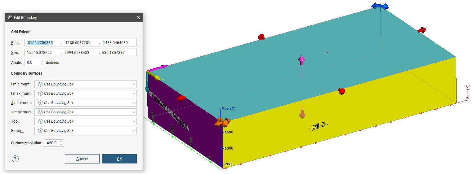
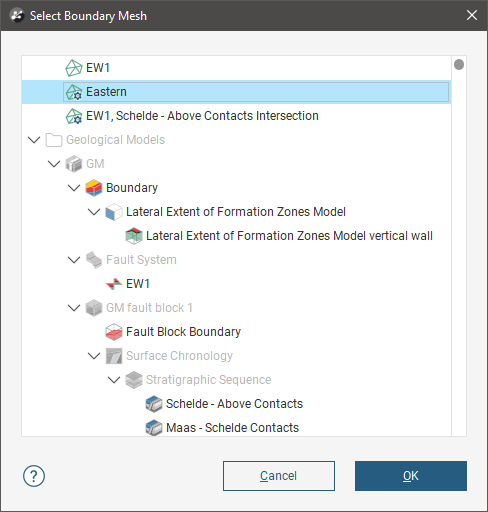
The boundary can also be modified by adding boundary surfaces. To add a boundary surface, right-click on Boundary, then select one of the options from the New Boundary menu. A window will appear containing all the objects of the selected type you can choose to add as a boundary extent. Select an object then click OK.
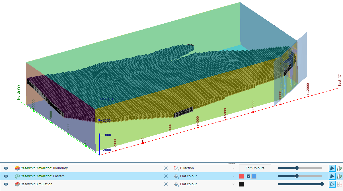
This adds the object as a boundary element, but it will be marked inactive in the project tree until it is used to edit the boundary. Double-click on the Boundary to open the Edit Boundary window again, then select the object as a Boundary surface using a relevant dropdown. Here J maximum is going to be modified using the Eastern mesh:
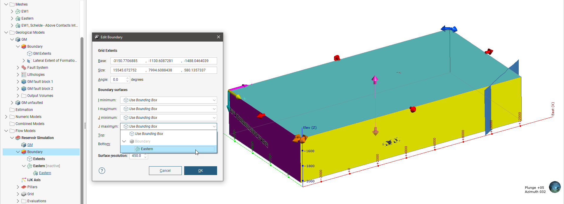
The resulting boundary is modified using the selected mesh as an extent:
As with other boundary objects, you can also Extract Mesh Parts, Extract Vertices and Export mesh parts of the boundary object, all options available in the right-click menu of the Boundary object.
Editing Pillar Spacings
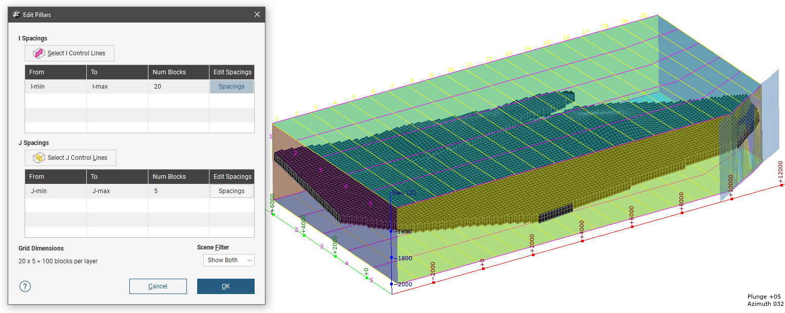
After a reservoir simulation model has been created, it is possible to modify the I and J pillar spacings for the model. In the project tree under the new reservoir simulation model, right-click on Pillars and select Open. In the Edit Pillars window, the number of blocks in the I and J directions can be modified by changing the Num Blocks values in the I Spacings and J Spacings tables. In the illustration below, the number of blocks in the I direction has been changed to 20 and in the J direction, 5.
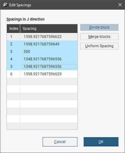
By default, the grid spacing is regular. To customise the pillar sizes, click a Spacings button. Select a row and change the Spacing value to modify the pillar dimension. The selected row will change in size, and the next adjacent row will grow or shrink accordingly.
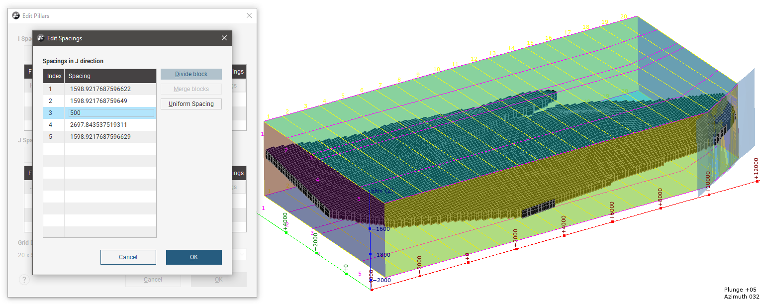
Select a row and click the Divide block button to halve the row, creating two rows where one used to be. This effectively increases the row count by one.
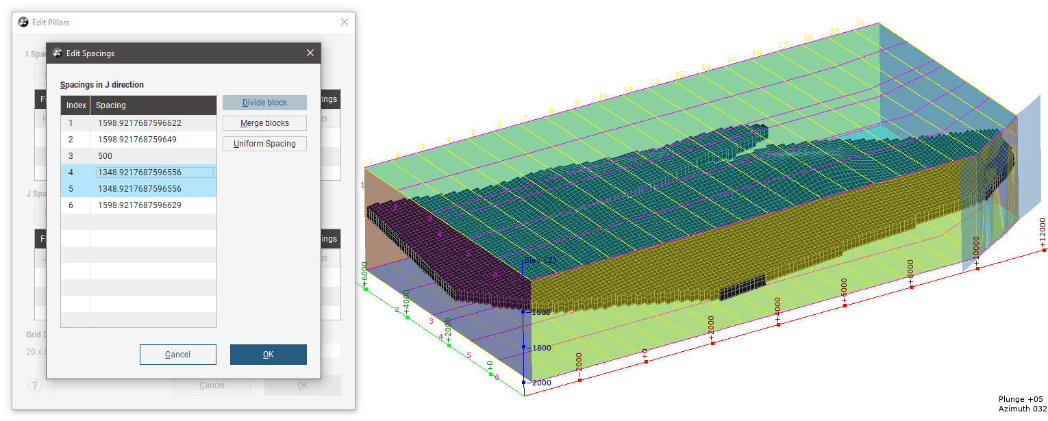
Multiple rows can be selected by selecting one row, then holding the Shift key while clicking on another row to select all the rows between. Click the Merge blocks button to combine them into a single row. Alternatively, you can click the Uniform Spacing button to combine the selected rows into a given number of rows with the same dimensions, without changing the total dimensions of the selected rows or the grid as a whole. You will be asked how many rows to form when using Uniform Spacing.
Adding Control Lines
Pillars are regularly spaced between the boundary extents or external control lines, unless the pillar spacings are manually set. The grid can additionally be divided using internal control lines, and the sections of the grid between control lines can be separately controlled to size pillars differently. In the project tree under the reservoir simulation object, right-click on Pillars and select Add Internal Control Line. Select the select From Fault or From Surface. In the Select Fault To Use or Select Surface To Use window that appears, select an object from the available objects than can be used to create control lines.
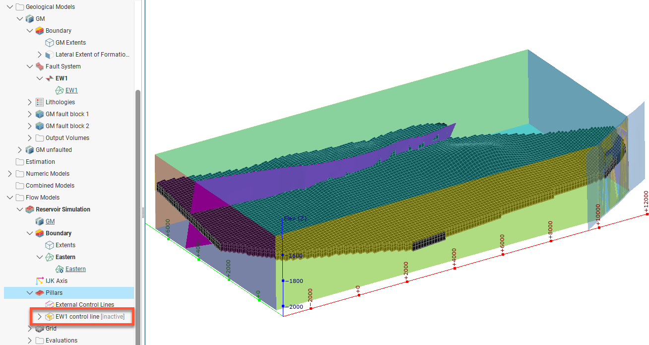
This adds the object as a control line, but it will be marked inactive in the project tree until it is selected to control pillar spacings. Double-click on Pillars to open the Edit Pillars window again. Click either the Select I Control Lines button or the Select J Control Lines button, then move objects from the Available Control Line list to the Selected Control Line list.
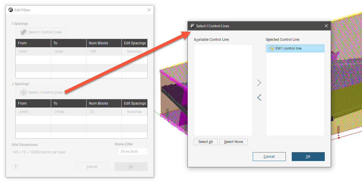
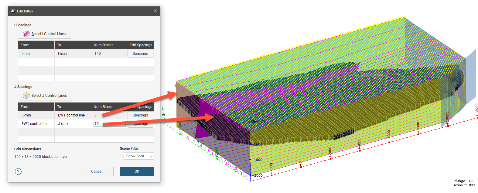
This will divide up the relevant spacings table into rows, dividing the grid into row sections that can be separately controlled. For instance, the number of blocks regularly dividing up each section can be different. Note also that if the control line is not straight, the resulting spacings will also follow the contours of the control line to maintain the regular default spacing.
Right-click on Pillars and select View All Control Lines to display all the control lines in the scene, coloured according to the I (magenta), J (yellow) and K (cyan) colours.
Editing the Grid Layers
After a reservoir simulation model has been created, it is possible to modify the grid layers for the model. In the project tree under the new reservoir simulation model, right-click on Grid and select Open. By default, layer guides are set from lithology contact surfaces, and two contact surfaces are used to limit the top and bottom of the grid. Disabling the use of these contact surfaces for top and bottom will result in the boundary extents being used for the top and bottom limits of the grid.
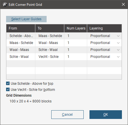
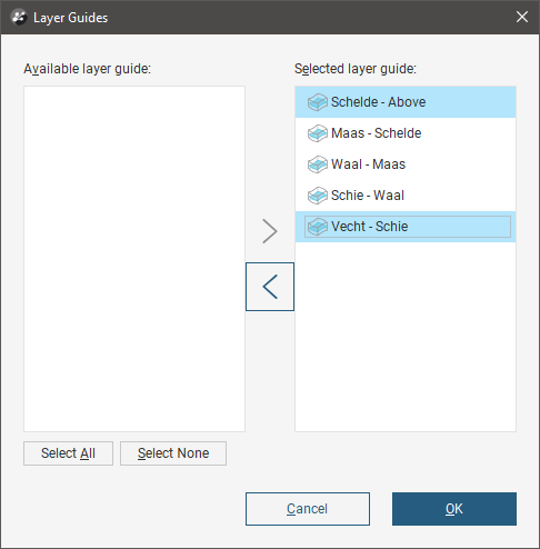
Click Select Layer Guides to change the selected layer guides. Contact surfaces can be selected and moved between the Available layer guide and Selected layer guide lists.
The Edit Grid window allows three different Layering options, Proportional, On Lap and Truncation. When dividing up a layer between two contact surfaces into several sub-layers determined by the specified Num Layers, the following strategies are used for each of these layering options:
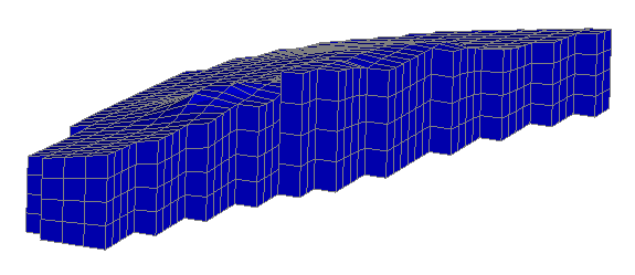
- Proportional. Each pillar has the same number of layers, proportionally sized to the distance between the two contact surfaces at the pillar location. As contact surfaces get closer together, the height of the layer blocks decreases.
- On Lap. The maximum distance between the contact surfaces, divided by the specified number of layers, is used to set the standard pillar block layer height. Pillar blocks are hung from the upper contact surface and are clipped short by the lower contact surface.
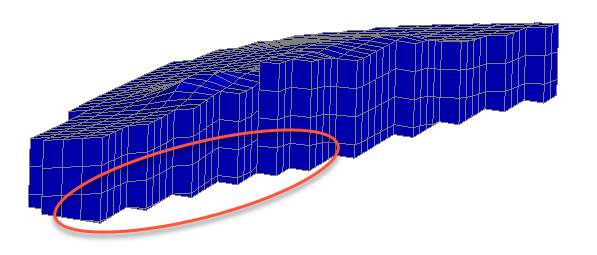
- Truncation. The maximum distance between the contact surfaces, divided by the specified number of layers, is used to set the standard pillar block layer height. Pillar blocks are stacked up from the lower contact surface and are truncated short by the upper contact surface.
Reservoir Simulation Evaluations
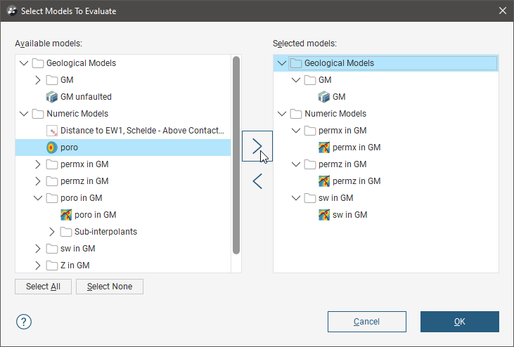
Right-click on a reservoir simulation in the project tree and click Evaluations. Select one or more evaluations in the Available models list and move them to the Selected models list to apply them to the reservoir simulation.
You can switch between the model evaluations using the colour options for the reservoir simulation in the shape list.
Setting Active and Pinchout Masks
Set grid masks for your reservoir simulation model by right-clicking on the reservoir simulation in the project tree selecting Set Active and Pinchout Masks. The following export dialog window will appear:
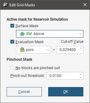
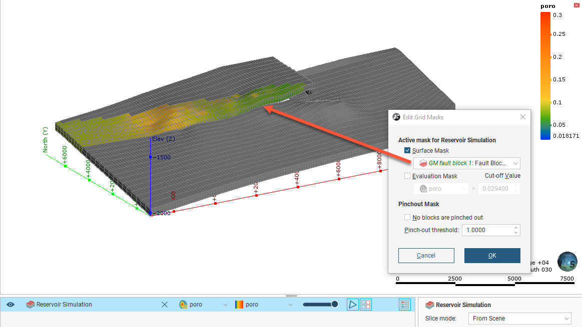
The top part of the dialog window has options for setting an Active mask for Reservoir Simulation. You can set either or both a Surface Mask and/or an Evaluation Mask.
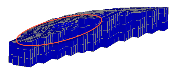
The Surface Mask option list will offer potential mesh surfaces that could be applied as a mask. Here a fault block boundary has been selected to mask off part of the reservoir simulation:
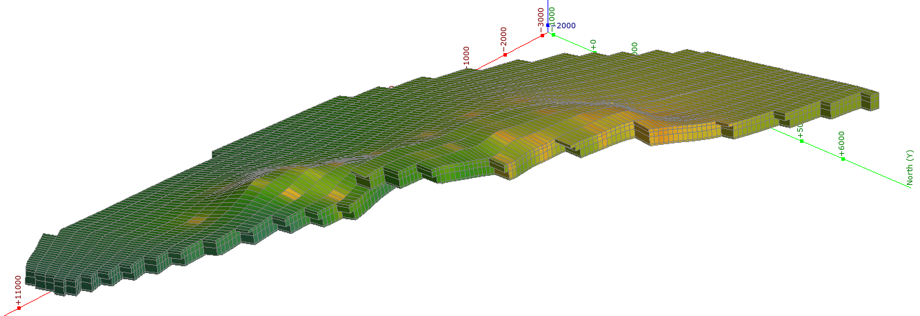
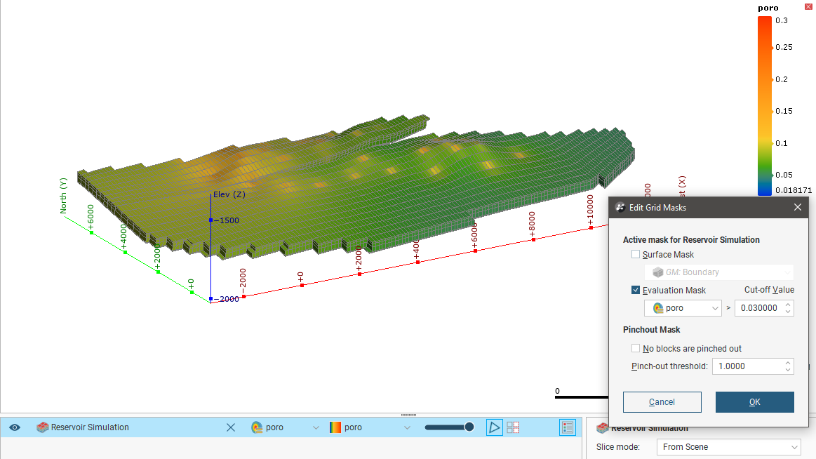
When selecting an Evaluation Mask, choose one of the available evaluations and set an appropriate Cut-off Value. Here a porosity evaluation has been used with different cut-off values to demonstrate the effect of the Evaluation Mask. First with a cut-off value of 0.03:
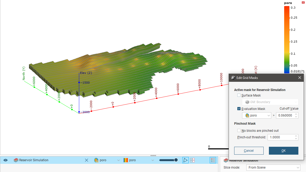
Here is the same view but with a cut-off value of 0.06. Note the model has fewer blocks, because more have been masked off with the more conservative cut-off value:
The lower part of the dialog window sets Pinchout Mask options. Tick the No blocks are pinched out checkbox to force no pinchout, or untick the box and specify a Pinch-out threshold to use.
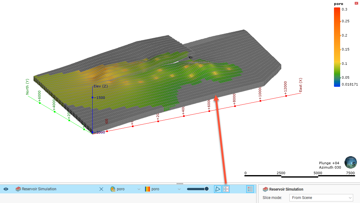
You can choose to Show inactive blocks or hide them by clicking the ![]() button in the shape list.
button in the shape list.
Exporting a Reservoir Simulation Model
Export your reservoir simulation model to a simulator tool by right-clicking on the reservoir simulation in the project tree then selecting Export to Reservoir Simulator. The following export dialog window will appear:
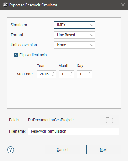
The Simulator dropdown has the CMG options IMEX, GEM and STARS along with an ECLIPSE option. If any of the CMG options are chosen, the Format can also be specified between Line-Based, Node-based and Corner-based. When ECLIPSE is selected, the format is automatically set to line-based.
The Unit conversion enables a Feet to Metres or Metres to Feet conversion for the export, depending on what units the model was used during modelling in Leapfrog Energy and what units are being used in the exported simulation, or select None for no conversion. You can also enable Flip vertical axis if you need to invert the vertical axis direction for the simulator.
Specify a Start date for the simulation using the Year, Month and Day fields.
Click Next to select properties to export.
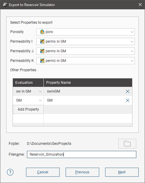
From the available evaluations, select the porosity and permeability properties for export. There is also a table where additional properties can be added, by clicking the Add Property button and selecting an evaluation.
Click Next when all properties to export have been selected.
The next step is to select which wells to export:
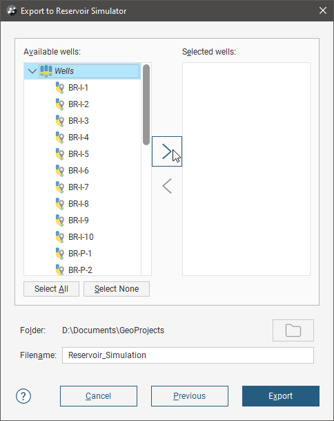
When you click the Export button, a series of files will be created in the selected folder. They will each have the Filename as the first part of the filename for each, with the end of the filename and the extension suffix differing depending on the role of each exported file.