
Meshes
In Leapfrog Energy, meshes are used to represent surfaces in the form of vertices and triangles that define the 3D shape of the surface. Meshes can be open or closed. Meshes are generated as part of the model-building process, but can also be imported into a project or created directly in the project. Leapfrog Energy has several tools for adjusting meshes.
The Meshes folder contains all meshes imported into Leapfrog Energy and created in Leapfrog Energy outside of the model building process.
Two types of meshes are stored in the Meshes folder:
- Non-editable meshes (
 ) are meshes imported into Leapfrog Energy and meshes created in Leapfrog Energy from the moving plane, Meshes > Mesh Operations tools and by extracting mesh parts from other surfaces in the project.
- Editable meshes (
 ) are created in Leapfrog Energy from data objects such as points data, GIS data and polylines. Editable meshes can be refined by adding more data. Editable meshes can be interpolated meshes (using FastRBF) or triangulated meshes (using Delaunay triangulation). Interpolated meshes can also be created from structural data and values objects.
The rest of this topic is divided into:
- Cleaning Up a Mesh
- Importing Meshes
- Reloading a Mesh
- Displaying Surfaces
- Assigning Attributes to Meshes
- Draping an Image on a Mesh
- Exporting Meshes
Cleaning Up a Mesh
There are several options for cleaning up a mesh that can be applied to meshes imported into Leapfrog Energy and to non-editable meshes created in Leapfrog Energy.
To clean up a mesh, double-click on the mesh in the Meshes folder or right-click on the mesh and select Open. The Cleanup Mesh window will be displayed:
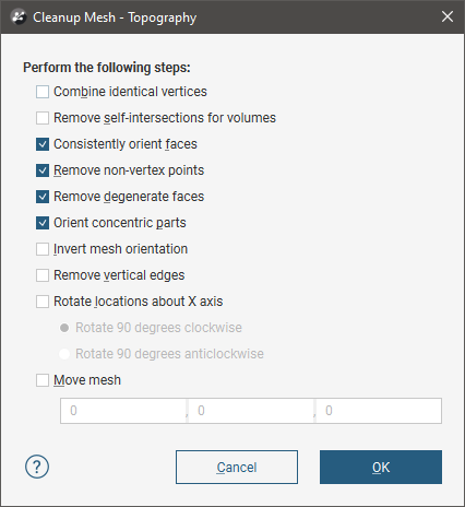
The Cleanup Mesh window will also be displayed when you import meshes.
The first option, Combine identical vertices, is intended for snapping cases where vertices occupy the exact same point in space. When enabled, vertices that have the exact same coordinates will be merged.
When enabled, Combine identical vertices occurs before the other processing actions in the Cleanup Mesh window.
The next option, Remove self-intersections for volumes, retriangulates self-intersecting triangles and trims away remaining open surfaces, whether they lie inside or outside the mesh. Before applying the Remove self-intersections for volumes option, check whether the mesh is open or closed. To do this, right-click on it in the project tree and select Properties. Closed should be True:
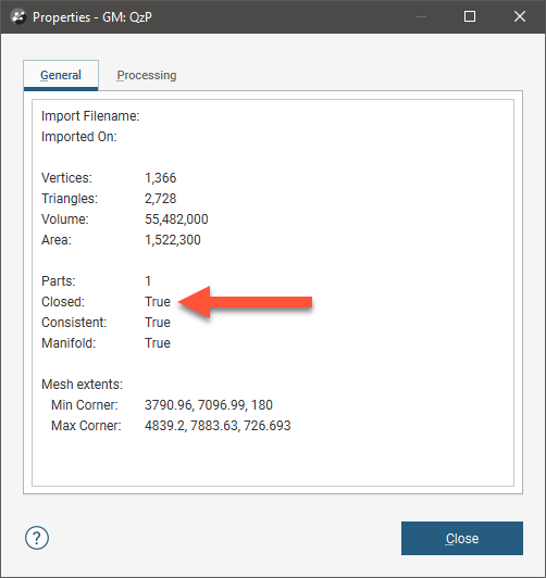
A mesh may appear to be closed in the scene but the Closed property will be false. Such a mesh may be made up of open parts that do not join up perfectly to make a closed mesh. If Remove self-intersections for volumes is enabled for such a mesh, it may disappear when it is trimmed.
Remove self-intersections for volumes should not be enabled for surface-like open meshes.
You may wish to enable Remove self-intersections for volumes if a mesh is reporting as open but is more volume-like than surface-like. Such a mesh may have a single open part that needs to be removed, or it may have open parts that line up perfectly and can be retriangulated to form a closed mesh.
The next four options are automatically applied to meshes created in or imported into Leapfrog Energy:
- Consistently orient faces ensures that a mesh can be used for inside/outside testing.
- Remove non-vertex points removes points that are not used by any triangles.
- Remove degenerate faces removes triangles with duplicate vertices.
- Orient concentric parts ensures that internal parts have the correct orientation.
Other options are:
- Invert mesh orientation reverses the polarity of the mesh.
- Remove vertical edges removes any vertical faces from the mesh boundary.
- Rotate locations about X axis lets you rotate the mesh 90 degrees clockwise or anticlockwise.
- Move Mesh lets you offset the mesh by a vector. Tick the Move Mesh box and enter the required values. The offset values can be changed by opening the Clean Mesh window once again.
Select the options required, then click OK.
The mesh will be added to the project tree under the Meshes folder.
Importing Meshes
Mesh formats Leapfrog Energy supports include:
- Alias Wavefront Object Files (*.obj)
- AutoCAD Drawing Files (2013/LT2013) (*.dwg)
- Bentley Drawing Files (v8) (*.dgn)
- DXF Polyface Files (11/12 [AC1009]) (*.dxf)
- Datamine Files (*.asc, *.dm)
- GOCAD Files (*.ts)
- Gemcom Files (*.tri)
- Leapfrog Energy Attribute Binary Mesh Formats (*.msh, *.ara)
- Leapfrog Model Files (*.lfm)
- Micromine Files (*.dat)
- Surpac DTM Files (*.dtm)
Once a mesh has been imported to the project, you can evaluate it against any interpolant or distance function in the project. See Evaluations for more information.
To import a mesh, right-click on the Meshes folder and select Import Mesh. Navigate to the folder that contains the mesh file and select the file. You can select multiple files using the Shift and Ctrl keys. Click Open to import the file.
The Cleanup Mesh window will be displayed. See Cleaning Up a Mesh. Select the options required, then click OK.
The mesh will be added to the project tree under the Meshes folder.
Meshes imported into Leapfrog Energy may exhibit geometries that cannot be used computationally by Leapfrog Energy. See Visualising Issues With Imported Meshes for information on how to identify issues with imported meshes.
Meshes With Textures
Leapfrog Energy can import OBJ meshes with textures. Image formats supported include:
- Graphics Interchange Format Files (*.gif)
- JPEG Files (*.jpg, *.jpeg)
- PNG Image Files (*.png)
- Tag Image Files (*.tiff, *.tif)
- Windows Bitmap Files (*.bmp)
The texture is automatically imported when the mesh is imported and will appear in the project tree under the mesh.
Reloading a Mesh
Meshes imported into Leapfrog Energy and created from extracting mesh parts can be reloaded. To do this, right-click on the mesh in the project tree and select Reload Mesh. Navigate to the file that should be used and click Open.
Displaying Surfaces
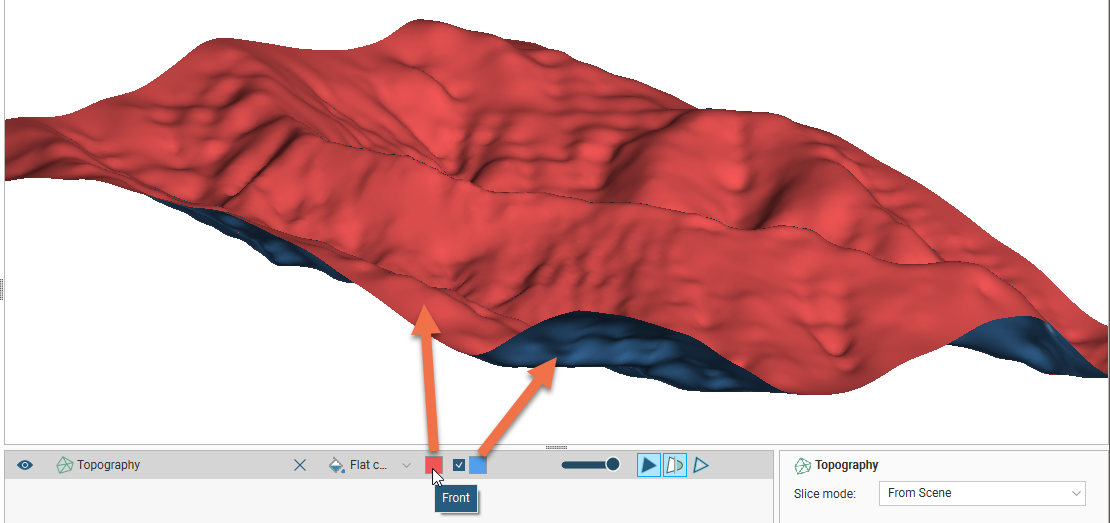
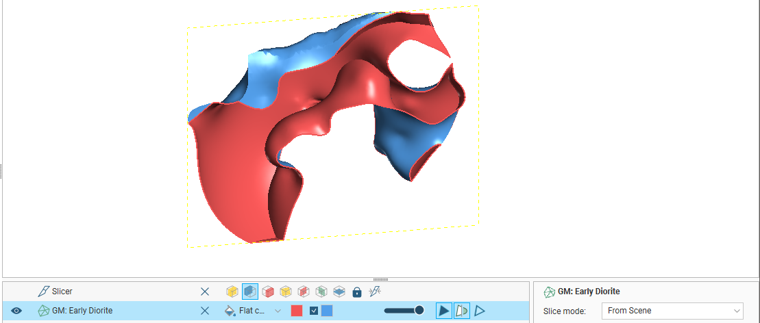
Leapfrog Energy assigns different colours to each side of a surface, according to the polarity of the surface.
See the Polarity in Leapfrog Energy for more information about the polarity of surfaces.
A basic mesh will have a front (coloured red) and a back (coloured blue) surface or an inside (red) and an outside (blue). For example, here an open mesh is coloured red on the upper/front and blue on the lower/back:
For a closed surface, these colours correspond to inside (red/warm) and outside (blue/cool):
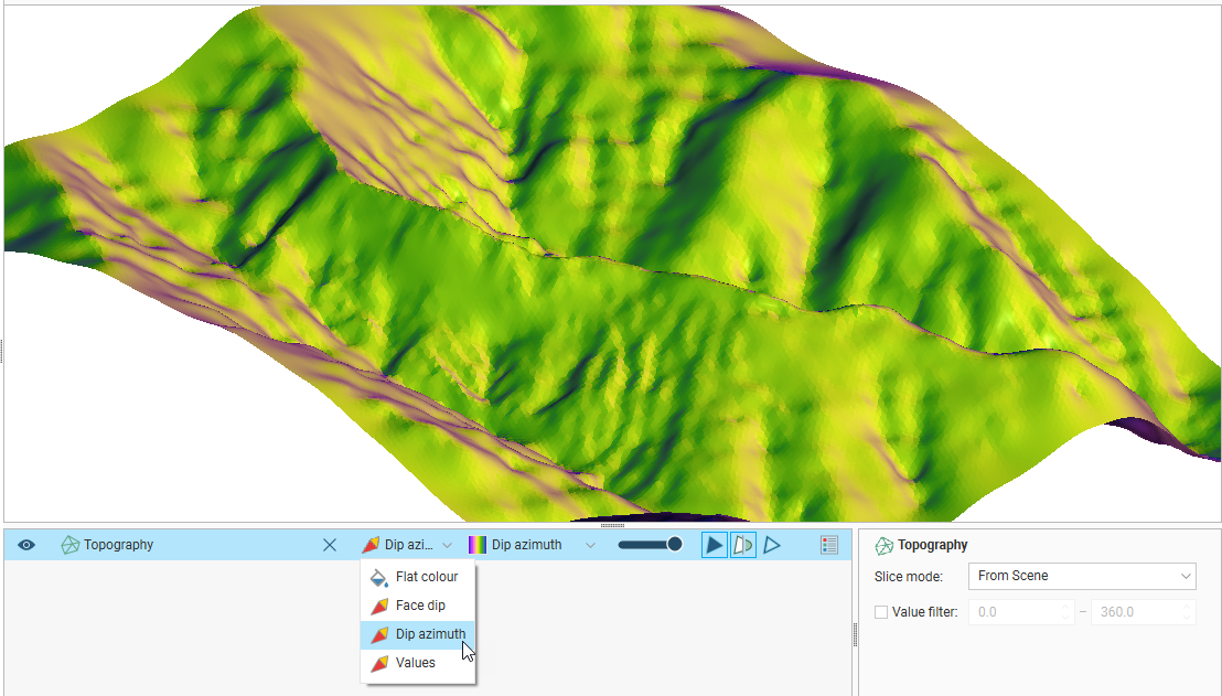
Many meshes in Leapfrog Energy can also be displayed using other properties, such as the Dip azimuth of the surface, which can be useful in highlighting areas of the surface that change direction rapidly:
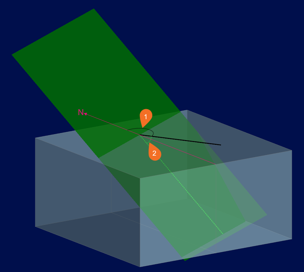
Dip azimuth is the angle between North and a line perpendicular to the strike, measured clockwise. In the following diagram, the dip azimuth is the angle marked (1), and the dip angle is marked (2).
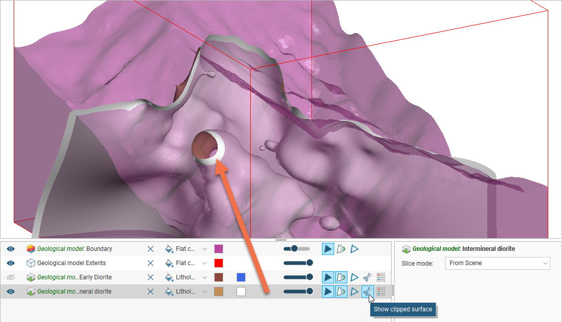
Surfaces that are part of a geological model or interpolant are, by default, displayed clipped to the model boundary. For example, here the Intermineral diorite surface is displayed clipped to the model boundary (pink):
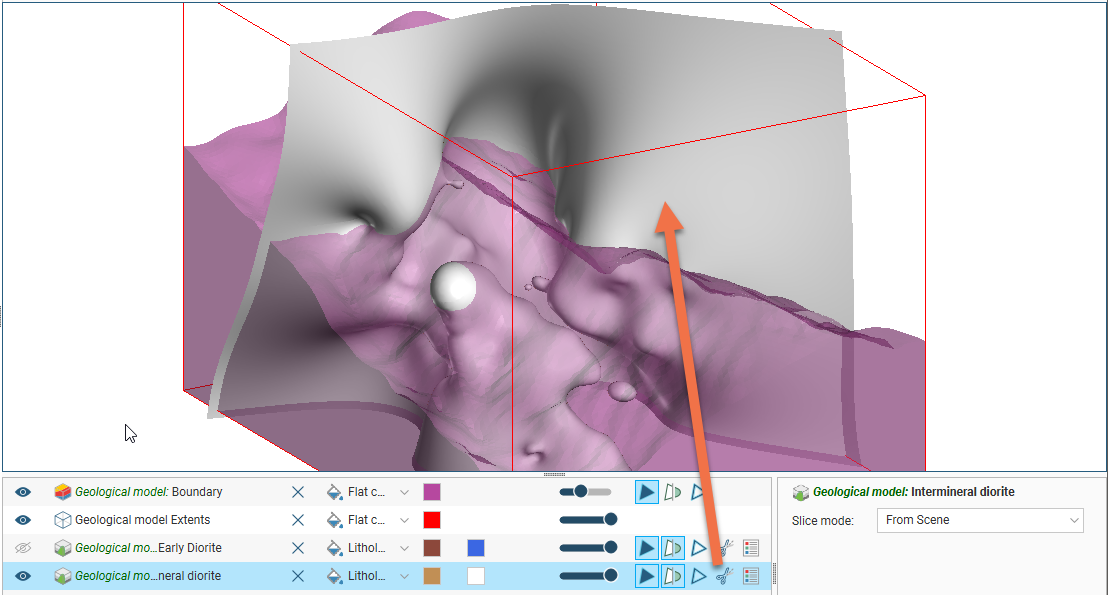
Disable the Clipped surface button ( ) to view the surface unclipped:
Leapfrog Energy supports the import of attributed meshes in GOCAD (*.ts) and Leapfrog Energy Attribute Binary Mesh (*.msh, *.ara) file formats. You can display such meshes using an attribute by selecting the attribute column from the view list.
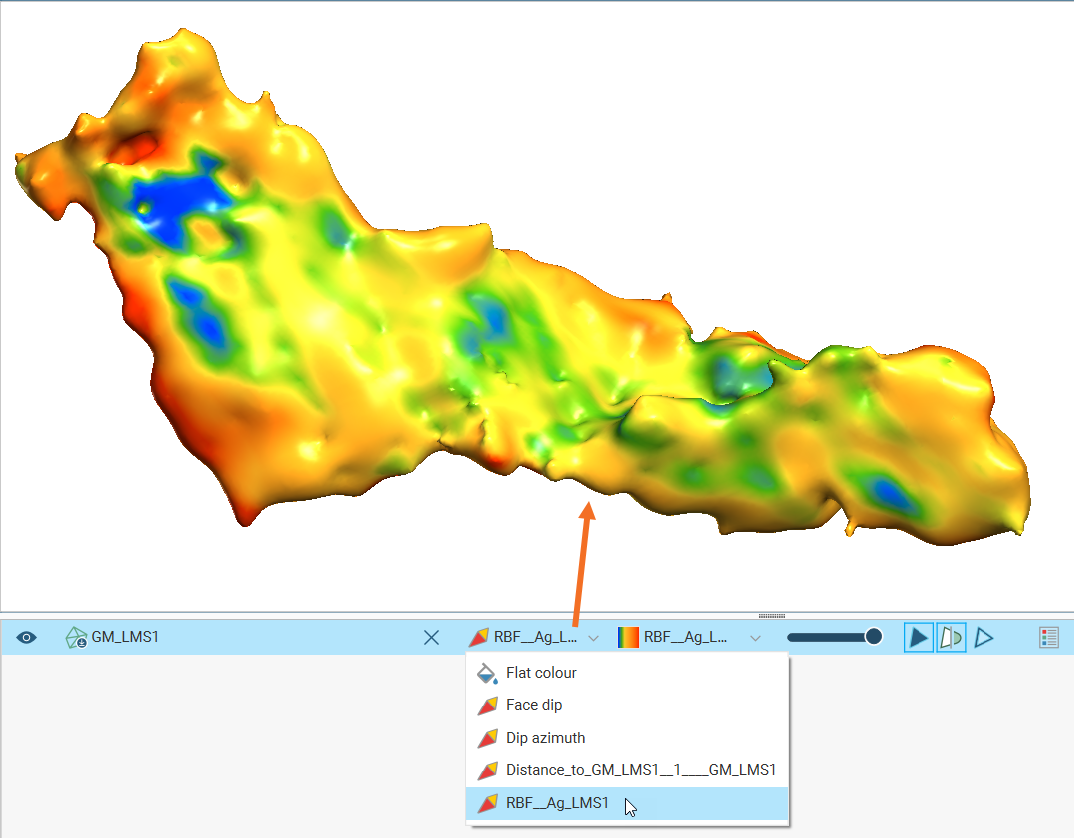
Only numeric attributes are supported on imported meshes.
Assigning Attributes to Meshes
You can assign attributes to a mesh, which adds a new column to the mesh object. To do this, right-click on the mesh in the project tree and select Attribute Table. In the window that appears, click the Add a new attribute column button ( ). In the window that appears, select the attribute type:
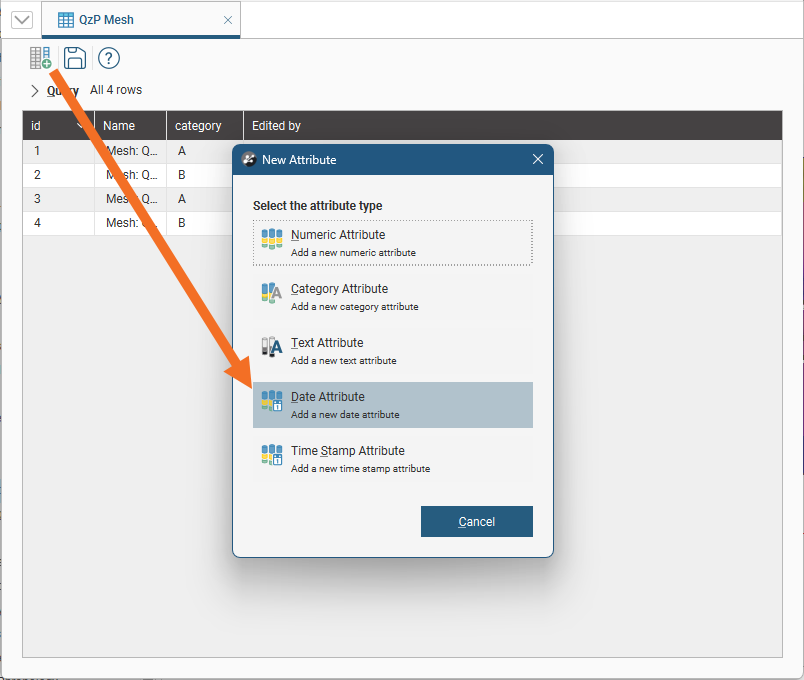
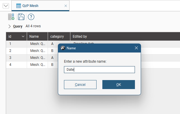
Enter a name for the column and click OK.
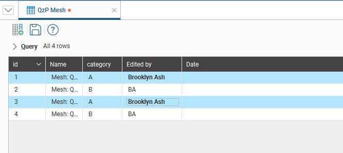
You can then add values for each cell in the new column by clicking in a cell to edit its contents. Recently edited cells are highlighted in bold until you save changes to the table.
You can multi-select lines to make bulk edits. Click and drag across rows down a column, or hold down the Ctrl key while clicking rows to select rows that are not contiguous. Click in one of the selected cells to make the change required to all selected cells.
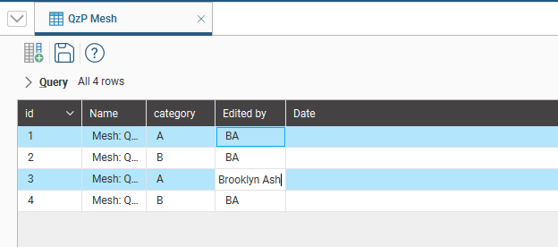
The edit will be applied to the same column in all the selected rows:
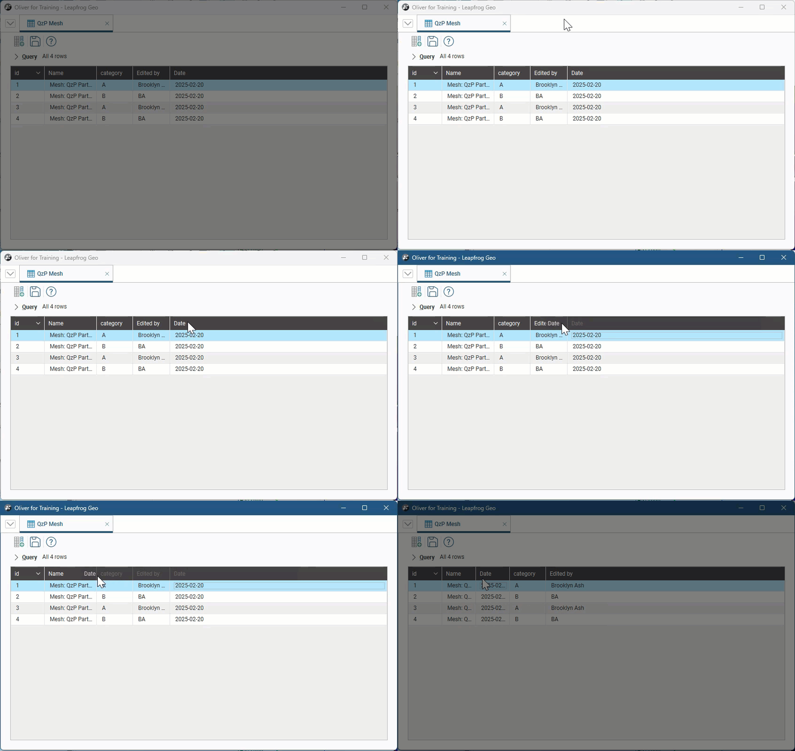
You can reposition the columns by clicking-and-dragging a column header to the required location and dropping it there:
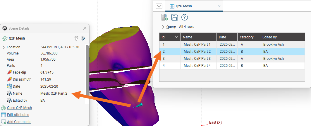
When you click in the scene, the values will be included in the information displayed about the mesh:
When you save scenes for viewing in Leapfrog Viewer, manually entered attributes will be displayed when volume information is displayed.
Draping an Image on a Mesh
You can drape images on any mesh in the Meshes folder. To do this, right-click on the mesh in the Meshes folder and select one of the Drape Image options.
- For the Import Image option, you will be prompted for a file location. Navigate to the folder containing the image you wish to drape, select the file and click Open. Set georeferencing information for the image, if required, then click OK. See Maps and Images for more information on georeferencing images. The imported image will appear in the project tree under the mesh.
- For the Select Existing Image option, select from the images available in the project and click OK. A hyperlink to the image will appear in the project tree under the mesh.
You can drape as many images as required. When the mesh is displayed in the scene, you will be able to select any draped images from the list of display options.
When you import and georeference an image, you can then export it as a GeoTIFF. To do this, right-click on it in the project tree and select Export. You will be prompted for a filename and location. Click Save.
Exporting Meshes
Leapfrog Energy exports meshes in the following formats:
- Leapfrog Attribute Binary Mesh Format (*.msh)
- GOCAD Files (*.ts)
- DXF Files (11/12 [AC1009]) (*.dxf)
- Gemcom Files (*.tri)
- Datamine Files (*_pt.asc, *_tr.asc)
- Micromine Files (*_MMpt.dat, *_MMtr.dat)
- Surpac Files (*.dtm, *.str)
- DXF Polyface Files (11/12 [AC1009]) (*.dxf)
- Alias Wavefront Object Files (*.obj)
- AutoCAD Drawing Files (2013/LT2013) (*.dwg)
- Bentley Drawing Files (v8) (*.dgn)
You can export single meshes or batch export meshes from the Meshes folder or from individual models. Each of these is described below:
- Exporting a Single Mesh
- Exporting Multiple Meshes from the Meshes Folder
- Exporting Multiple Meshes from Models
Exporting a Single Mesh
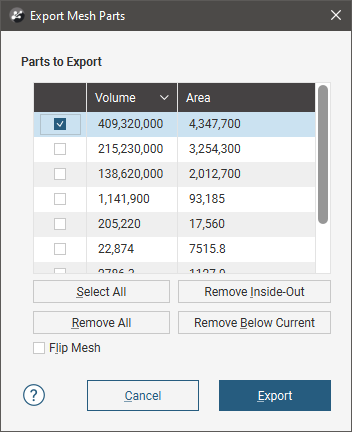
To export a mesh, right-click on the mesh and select Export. The Export Mesh Parts window will appear:
An Export clipped mesh option is available for meshes that are clipped to a boundary:
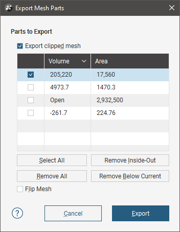
If the quality of the mesh produced is not acceptable, clip the mesh as described in Clipping a Mesh, then export the mesh.
Select the Parts to Export, then click OK. You will be prompted for a filename and location.
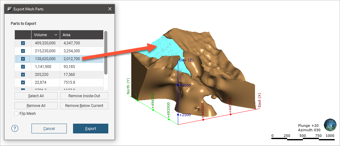
When exporting a mesh that has multiple parts, you can distinguish between the different parts by clicking on them in the Export Mesh Parts window. Here, the mesh was added to the scene before the Export Mesh Parts window was opened. Clicking on a mesh part in the list selects that part in the scene:
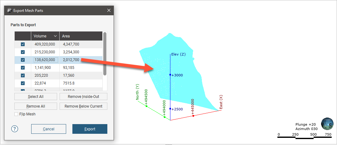
If the mesh is not in the scene when the Export Mesh Parts window is opened, selecting a part in the list will display it in the scene without reference to the other parts of the mesh:
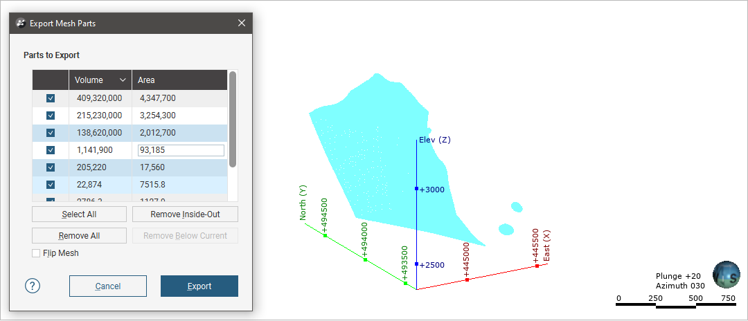
Use the Shift and Ctrl keys to select and view multiple mesh parts in the scene:
Exporting Multiple Meshes from the Meshes Folder
To export multiple meshes from those in the Meshes folder, right-click on the Meshes folder and select Export Meshes. In the window that appears, select the meshes you wish to export:
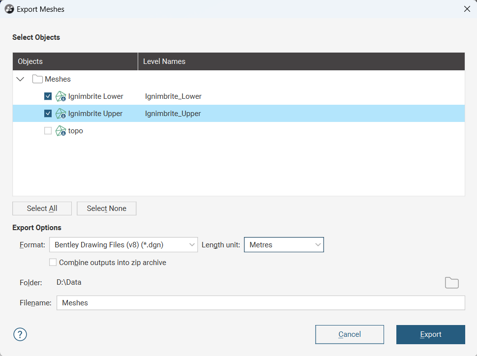
The filename that will be used for each mesh is shown in the Filenames column. To change the filename for any of the meshes, click on its name in the Filenames column.
Next, select the format required and where to save the exported meshes. Available formats for bulk export are:
- Leapfrog Model Files (*.lfm)
- Leapfrog Attribute Binary Mesh Format (*.msh)
- GOCAD Files (*.ts)
- DXF Files (11/12 [AC1009]) (*.dxf)
- Surpac Files (*.dtm, *.str)
- Gemcom Files (*.tri)
- Datamine Files (*_pt.asc, *_tr.asc)
- Micromine Files (*_MMpt.dat, *_MMtr.dat)
- DXF Polyface Files (11/12 [AC1009]) (*.dxf)
- Alias Wavefront Object Files (*.obj)
- AutoCAD Drawing Files (2013/LT2013) (*.dwg)
- Bentley Drawing Files (v8) (*.dgn)
When exporting in Bentley Drawing Files (v8) (*.dgn) format, a Length unit needs to be specified.
For any of the export options other than Leapfrog Model Files format, you can select Combine outputs into zip archive to save the meshes as a zip file.
Click Export to save the meshes.
Exporting Multiple Meshes from Models
You can export multiple meshes from individual geological models, numeric models, combined models and static models. To export meshes in this way, right-click on a model or interpolant and select Export. In the window that appears, select the volumes and surfaces you wish to export:
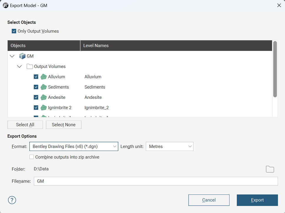
For geological models, if you wish to export surfaces other than the output volumes, untick the Only Output Volumes option.
For faulted geological models, you also can select from the faulted volumes by ticking the Faulted Volumes box:
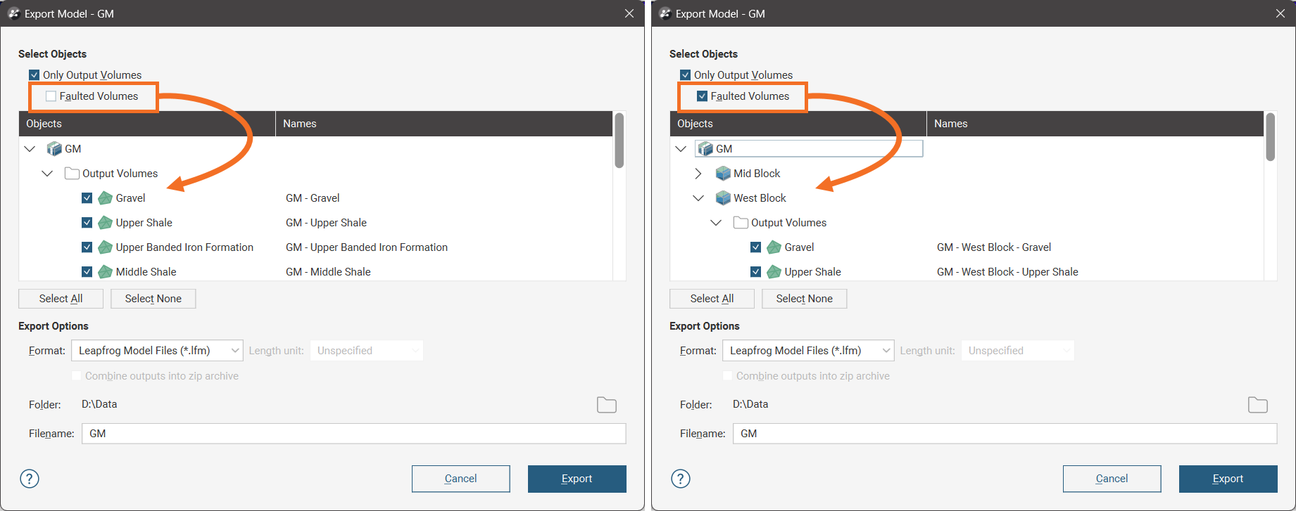
The filename that will be used for each mesh is shown in the Filenames column. To change the filename for any of the meshes, click on its name in the Filenames column.
Next, select the format required and where to save the exported meshes. Available formats are:
- Leapfrog Model Files (*.lfm)
- Leapfrog Attribute Binary Mesh Format (*.msh)
- GOCAD Files (*.ts)
- DXF Files (11/12 [AC1009]) (*.dxf)
- Surpac Files (*.dtm, *.str)
- Gemcom Files (*.tri)
- Datamine Files (*_pt.asc, *_tr.asc)
- Micromine Files (*_MMpt.dat, *_MMtr.dat)
- DXF Polyface Files (11/12 [AC1009]) (*.dxf)
- Alias Wavefront Object Files (*.obj)
- AutoCAD Drawing Files (2013/LT2013) (*.dwg)
- Bentley Drawing Files (v8) (*.dgn)
For any of the export options other than Leapfrog Model Files format, you can save the meshes as a zip file.
The Leapfrog Model File format exports a single *.lfm file. If the file is imported into the Meshes folder, each output volume will appear as a single mesh.
Click Export to save the meshes.