Planning Single Drillholes

This topic describes how to create and edit a single drillhole as part of a drillhole group. See Drillhole Planning Groups for an overview of working with drillhole groups in Leapfrog Energy.

To create a new drillhole in a drillhole group using the single hole method, add the data objects to the scene that you will use in defining the planned drillholes, such as any existing drillholes and surfaces that represent the collar and target locations. Open the drillhole group or create a new one by right-clicking on the Planned Wells folder and selecting New Drillhole Group.

Set the Prefix to be used for each drillhole that will be added to the group, and update the drilling defaults, if necessary.

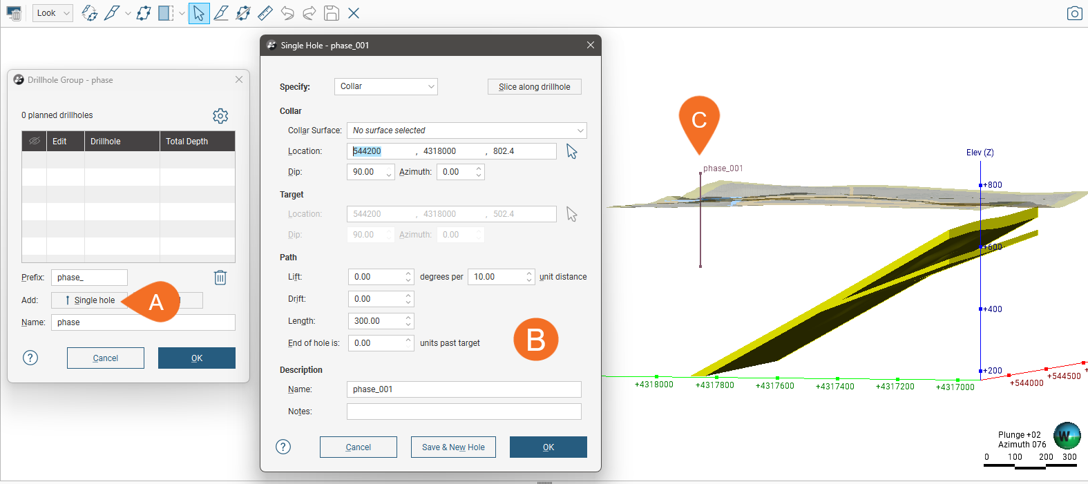
To add the first drillhole, click the Single hole button (A). This opens the Single Hole window (B), with an initial drillhole displayed in the scene (C).

Clicking the Single hole button in the Drillhole Group window, marked A, opens the Single Hole planning window, marked B, and puts an initial vertical drillhole in the scene, marked C

The new drillhole has a Name that uses the Prefix set in the Drillhole Group window. You can add a Note about this drillhole that will be visible in the scene details panel when the drillhole is clicked on in the scene.

This initial drillhole uses the default planning mode and the parameters set for the project in the Drillhole Planning Options window.

As you work in this window, note that the changes you make to:

  • The planning mode
  • The Collar Surface
  • The Path settings

will be retained when you click Save & New Hole in order to create another drillhole. This makes it easy to set up a series of planned drillholes. You can change the default values used for the first drillhole in the Drillhole Planning Options window.

There are three planning modes you can use in this window, specifying the Collar, specifying the Target or specifying both Collar & Target.

The planning mode determines which parameters you can change in this window:

  • For Collar mode, you cannot edit the target’s settings, which are calculated from the collar and path settings.
  • For Target mode, you cannot edit the collar location as that will be calculated from the target and path information.
  • For Collar & Target, you cannot edit the dip and azimuth values for the collar and target, as these are determined by Leapfrog from the collar, target and deviation parameters. In rare cases where the path cannot be calculated, perhaps because the curvature is too high for the collar-to-target distance, you will see an error.

Whichever mode you are using, you can choose a Collar Surface that will be used in setting the collar elevation.

If the collar does not intersect the selected Collar Surface, an error message will be displayed. Either move the drillhole so that it intersects the surface or switch to using no surface.

To specify the collar and/or target location you can:

  • Enter coordinates in the Single Hole window.
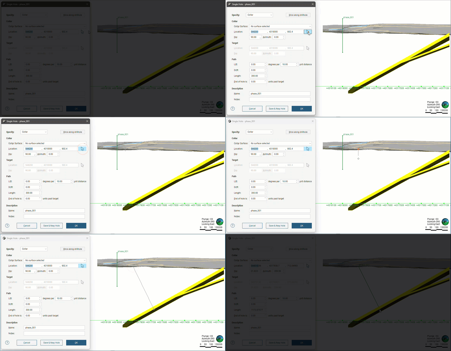
  • Click on the button for the collar/target and then click in the scene where you wish to add the collar/target.

Entering coordinates and clicking in the scene both set the collar or target location in the scene and display a path calculated using the parameters in the Single Hole window. In both cases, drawing a slice in the scene can help in adjusting the drillhole and in defining subsequent drillholes. To do this, click the Slice along drillhole button

You can also use the collar/target button to ‘draw’ the path of the drillhole in the scene. To do this, click the button for the collar/target, then click in the scene without releasing the mouse button. Drag to define the Path and release the mouse button when you have reached the target.

Once you have finished defining the drillhole, you can save the drillhole and close the planning window or keep the planning window open and create a new drillhole.

  • To keep adding drillholes to the drillhole group, click Save & New Hole. The current drillhole will be saved and the Single Hole window will open for a new drillhole created at the Offset To Next Hole distance specified in the Drillhole Planning Options window. The planning mode, Collar Surface and Path settings used will be those used for the previous hole.
  • To close the current drillhole, click OK. The drillhole will be saved to the group and its window closed, returning you to the Drillhole Group window.

The illustrations that follow show planning a drillhole by specifying the collar location, but the information also applies to planning using the other modes.

Here the planning mode (D) is Collar and the initial Location values (E) create a drillhole in the scene (F):
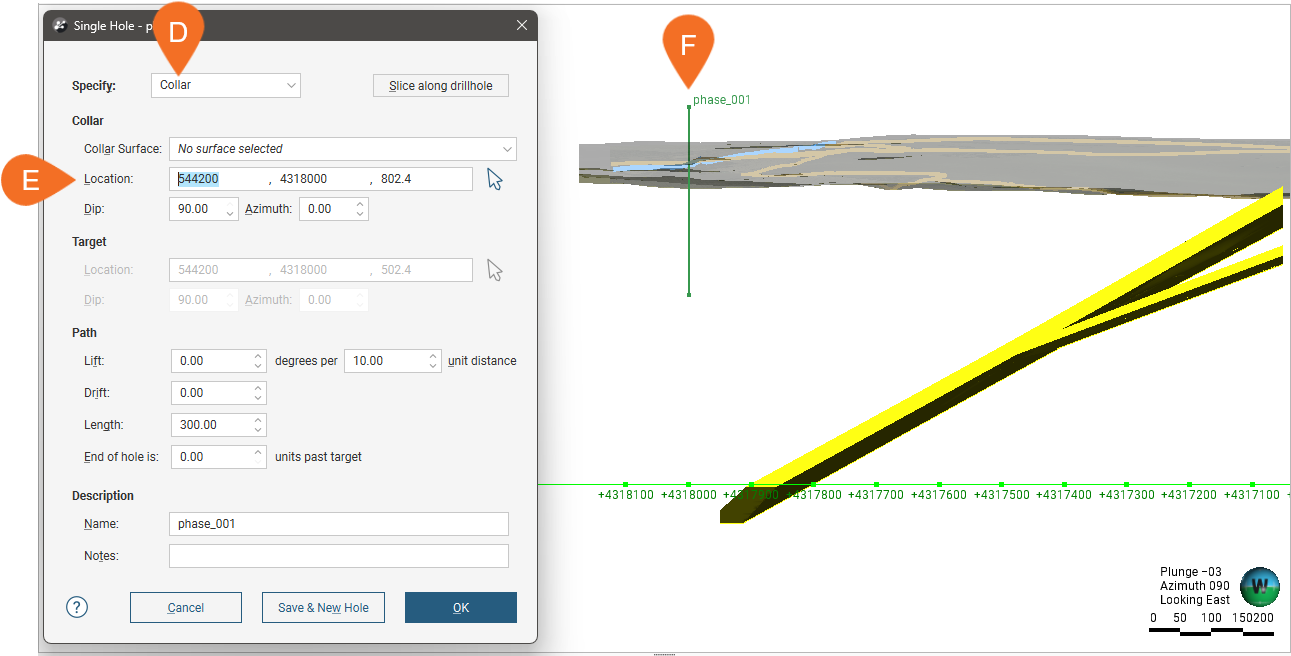
The Single Hole window with the planning mode marked D, the collar location values marked E, and the resulting vertical drillhole in the scene marked F, its collar sitting above the topography

Note that the collar location is above the topography surface displayed in the scene. To make sure the location lies on the topography, select a surface from the Collar Surface list (G):
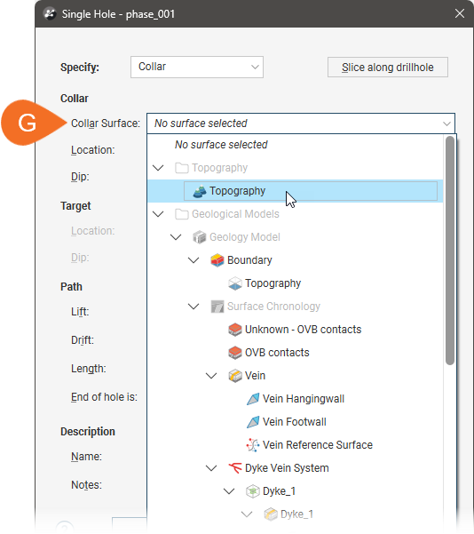
The Collar Surface list marked G open in the Single Hole window, with the project's Topography surface being selected so the collar is placed on it

This moves the collar onto the selected surface.