
Plan View Layouts
Plan view layouts are similar to section layouts, with a couple of specific differences enumerated below. For all other layout editor behaviour, refer to the Section Layout Editor topic.
Creating Plan View Layouts for Plan Views
A plan view is a special type of horizontal section providing projected map imagery and other details to provide a wide contextual overview. Plan views have their own plan view layouts; section layouts cannot be applied to plan views.
If there is no existing plan view, first add a model to the scene and press the D key to get a top-down view of the model. Next, right-click on the Sections, Plans and Contours folder and select New Plan View. The New Plan View window will appear, together with a plan view plane and controls in the scene that let you adjust the position of the plan view plane:
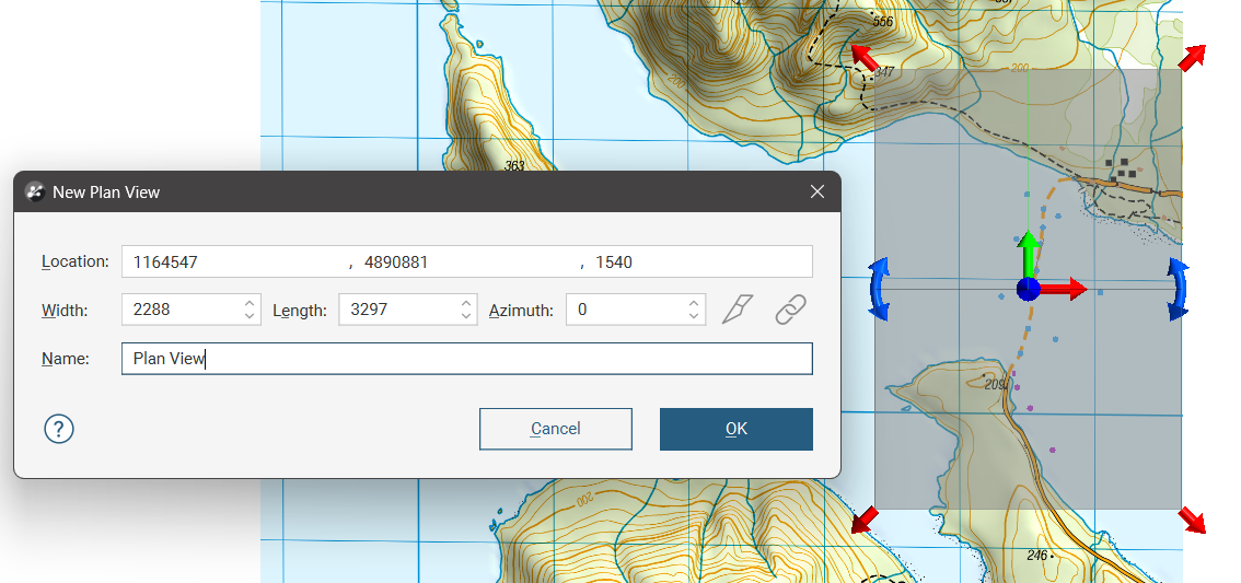
Use the handles in the scene to position and size the plan view plane. The handles work in the same manner as the moving plane controls, as described in The Moving Plane.
Switch to a side view to set the elevation of the plan view. Use an elevation over the project area if you are creating a plan view purely for context, or choose a specific elevation in the project space to view horizontal sections through the scene.
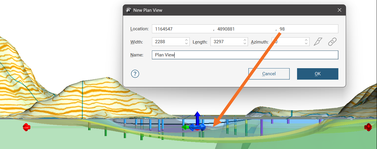
Once the plan view plane is positioned as required, click OK to create the new plan view, which will appear in the Sections, Plans and Contours folder. Right-click on the plan view in the project tree and select New Layout. A new plan view layout window will open.
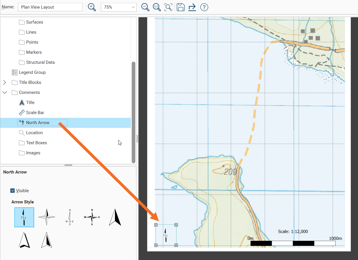
Plan view layouts are similar in most respects to section layouts, except plan views can also have a North Arrow feature added to them from the Comments folder.
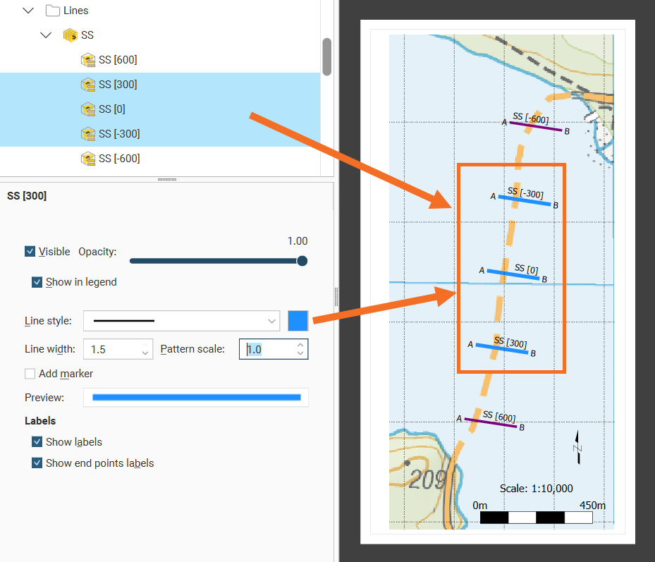
Along with other line colour, style and width controls, section lines can have their labels positioned to the Left, Centre or Right by clicking through to the labels options.
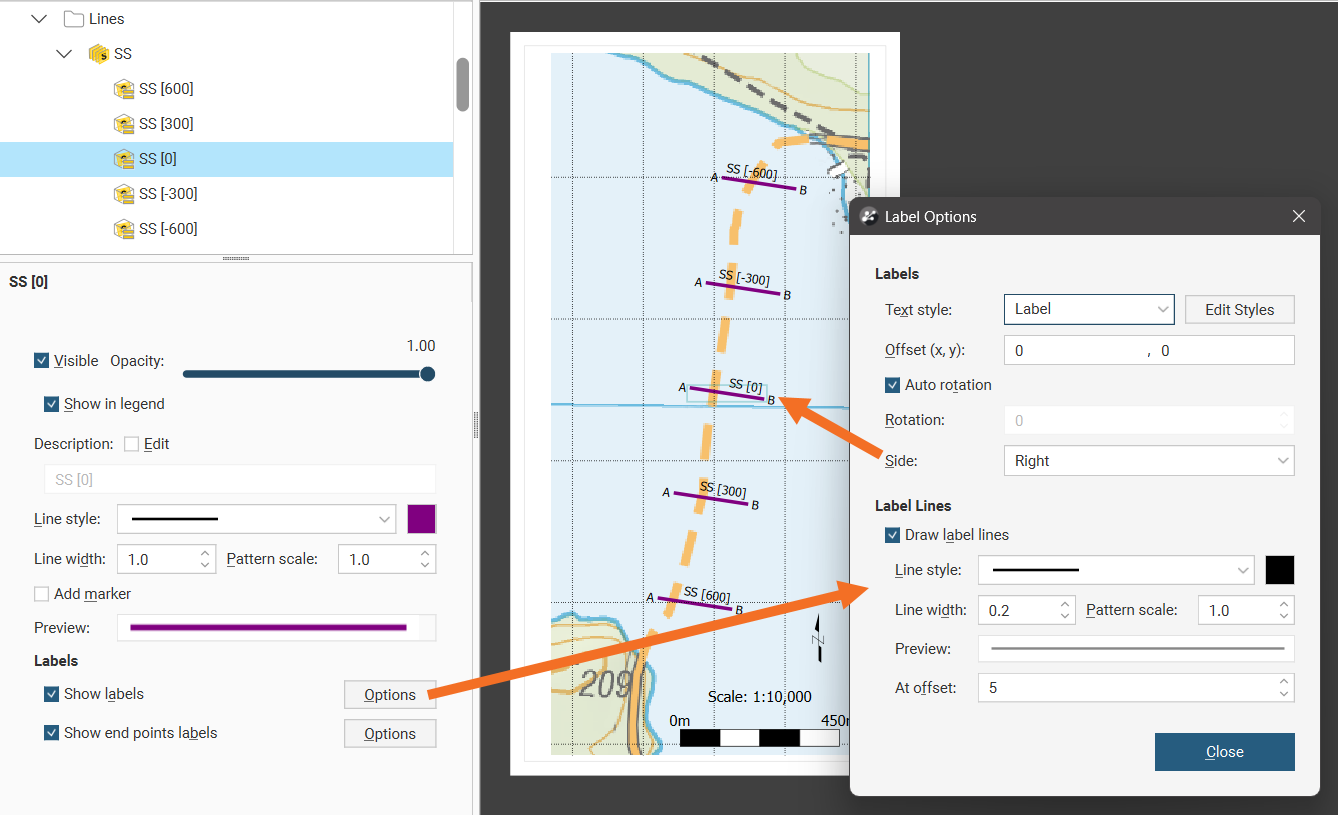
You can select multiple lines by holding down the Shift key or the Ctrl key while clicking. You can then style the selected lines similarly without having to make individual customisations to each line.
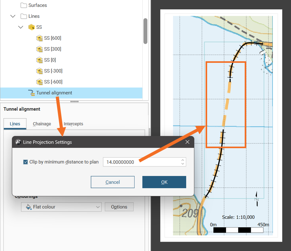
Lines projected onto the plan view can be clipped to parts of the line within a clipping distance. Double-click on the line object or right-click on the line object and select Projection settings, then tick Clip by minimum distance to plan and specify a clipping distance. Here the minimum distance selected is less than the distance the tunnel alignment line drops below the plan view elevation, so part of the tunnel alignment is not shown on the plan view:
In other respects, plan view layouts are similar to section layouts, and the guidance for the section layout editor applies to the plan view editor also. For more information on using the section layout editor, see the Section Layout Editor topic.
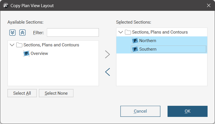
Plan view layouts can be reused and modified for other plan views. When multiple plan views are available, right-click on a preferred plan view layout in the project tree and select Copy Layout To. The Copy Plan View Layout window will show the Available Sections. Move plan views over to the Selected Sections list to apply the plan view layout.
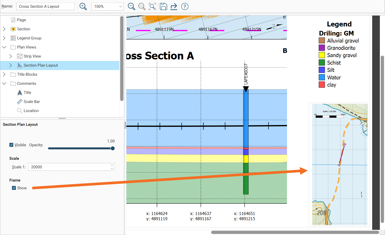
Once created, a plan view can be added to a section layout from the Plan Views folder. Right-click Plan Views in the layout tree and select Add Plan View. The Add Plan View window will appear, listing the available options for plan view layouts. Select one and click OK.
One setting unique to plan views is the Show checkbox in the Frame section. This will add a thin box around the outside of the plan view to visually separate it from the rest of the section layout.
Exporting Plan View Layouts
Once you have finished adjusting the plan view layout, you can export it in one of the following formats:
- PDF Files (*.pdf)
- Scalable Vector Graphics Files (*.svg)
- PNG Image Files (*.png)
- GeoTIFF Files (*.tiff, *.tif)
Click the Save and Export button ( ) at the top of the window or right-click the plan view layout in the project tree and select Export Layout from the pop-up menu. You will be prompted for a filename and location.
You can also batch export multiple section layouts including plan view layouts. To do this, right-click on the Sections, Plans and Contours folder and select Batch Export Layouts. All selected sections can be exported as a single PDF or individually in PDF file (*.pdf), Scalable Vector Graphics file (*.svg), PNG image (*.png) or GeoTIFF (*.tiff, *.tif) formats. When section layouts are exported individually, all outputs can be combined into a zip archive.
In the window that appears, select the layouts you wish to export, then select a format. If you select a format other than Single PDF, you can combine all outputs into a zip archive. Select where you wish to save the outputs, then click Export.
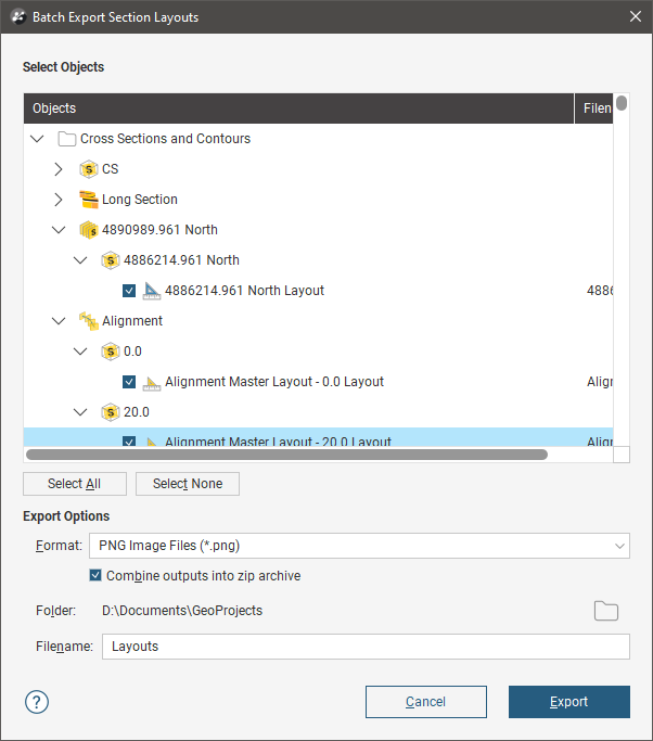
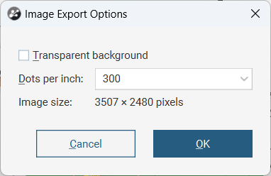
If the export format is selected as a GeoTIFF file, an Image Export Options window will appear where the resolution can be specified in Dots per inch and you can specify whether or not the image will have a Transparent background.
The export will be processed as a background task that appears in the processing list.