Modifying Surfaces
This topic describes aspects of modifying surfaces in Leapfrog Geo. It is divided into:
- Adding Data to Surfaces
- Honouring Surface Contacts
- Editing Surfaces With Polylines
- Editing Surfaces With Structural Data
- Modifying Surfaces With Anisotropic Trends
- Applying a Structural Trend
Trends can also be applied to reshape surfaces. For more information on the concept of trends, see Trends and Anisotropy.
Adding Data to Surfaces
Many surfaces can be refined by adding points, structural data, GIS data and polylines. If a surface can be modified in this way, an Add menu will appear for the object when you right-click on it in the project tree. For example, the Add menu for this contact surface shows the data types that can be used to refine the surface:
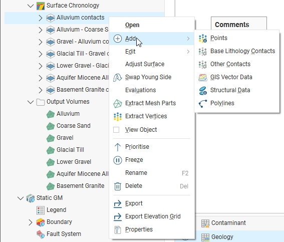
Select the type of data you wish to use to modify the surface. Leapfrog Geo will display all the suitable objects in the project. Select the required object and click OK. A hyperlink to the added data will appear under the surface in the project tree. The added data can be removed from the surface by expanding the surface in the project tree, then right-clicking on the hyperlinked data object and selecting Remove.
Honouring Surface Contacts
In Leapfrog Geo, surfaces can be created from drilling data, points data, structural data, GIS data and polylines. When surfaces are created from several different objects, it may be desirable to snap the surface to some data objects but not to others.
There are several options for snapping surfaces to data:
- Off. The surface does not snap to the data used to create it.
- All data. The surface snaps to data within the Maximum snap distance, which includes drilling data and any data added to the surface.
- Drilling only. The surface snaps to drilling data and data objects derived from drilling data within the Maximum snap distance but not to other data used to modify the surface. For example, the surface will honour points data derived from drilling data, but not points data imported into the Points folder.
- Custom. The surface snaps to selected data objects within the Maximum snap distance.
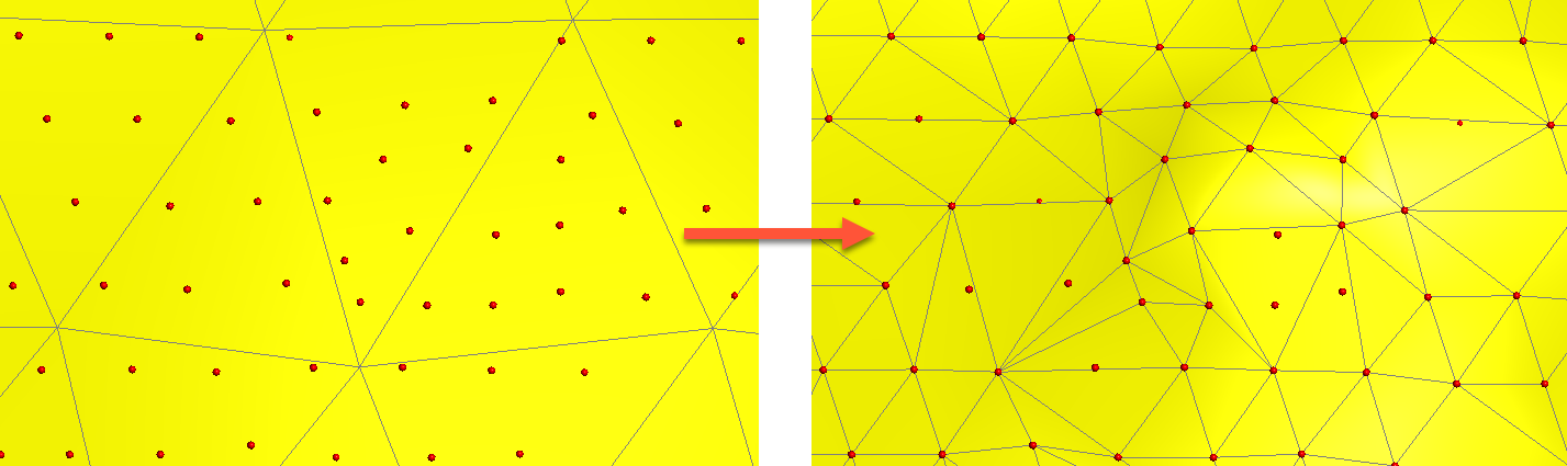
Snapping forces surfaces to honour the specified contacts, moving triangles on the surface so that the surface precisely intersects the contact. For example, snapping is disabled for the surface on the left, but enabled for the surface on the right. The points used to generate the surface are shown in red, and the triangles are displayed so you can see how snapping to data affects the surface:
When snapping is enabled, the Maximum snap distance is used to determine what data should affect the surface. The Maximum snap distance is, by default, set to half of the Surface resolution setting, but you can adjust that up or down, if required.
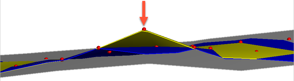
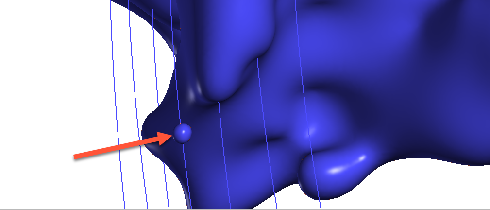
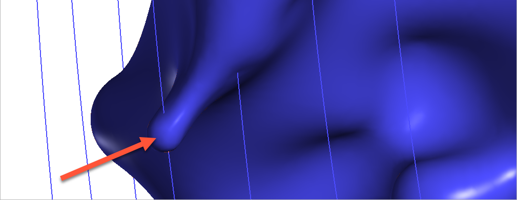
In this image, three surfaces are shown, along with the points used to generate the surface (red). The grey surface is the surface that results when snapping is Off. For the yellow surface, snapping to the points is enabled and the Maximum snap distance has been set to a high value, resulting in the yellow surface snapping to the distant point indicated by the arrow. Snapping to points is also enabled for the blue surface, but the Maximum snap distance has been set to a lower value, so that the surface snaps to some close points, but does not snap to the distant point.
While the most suitable snapping option is always project- and purpose-specific, if you have sufficient drilling data, snapping to Drilling only is recommended. This option gives the highest priority to the input data itself while still allowing the surface to be influenced by manual interpretations. Contrary to the All data snapping option, the Drilling only option also reduces the potential for complications resulting from contradictory data (e.g. the drilling data indicates a surface contact is in one place, but a polyline indicates it’s somewhere else).
Take care in enabling snapping and in selecting what data the surface will snap to, as the more data you include, e.g. by setting a large Maximum snap distance or selecting All data for Snap to data, the greater the possibility that errors in the data or assumptions inherent in interpretations (e.g. polylines) will cause distortions in the meshes. If you do enable snapping, it is best to snap only to drilling data.
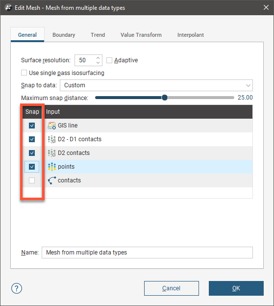
For example, here the Snap to data has been set to Drilling only for a mesh created from multiple data objects:
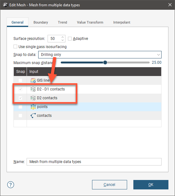
Note that the only objects Snap is enabled for are the contacts derived from drilling data.
Here, Snap to data has been set to Custom, which makes it possible to enable Snap for only the selected data objects:
In Leapfrog Geo, the snap settings for different types of surfaces can be controlled as follows:
- For geological models, Snap to data can be set for the model as a whole, but individual surfaces can have different settings. For more information, see:
- For editable interpolated meshes and offset meshes (
 ), Snap to data can be set by double-clicking on the mesh and changing the settings in the General tab. See Refining an Interpolated Mesh and Offset Meshes for more information.
Editing Surfaces With Polylines
In Leapfrog Geo, many surfaces can be edited using polylines, including contact surfaces, geological model extents and editable meshes.
To edit a surface with a polyline, it is a good idea to first add the object you wish to edit to the scene and draw a slice across the scene where you plan to edit the surface. Next, right-click on the surface in the project tree and select Edit > With Polyline.
The drawing toolbar will appear for the type of polyline selected and a new polyline will be added to the scene. Draw the polyline and adjust it as described in Drawing in the Scene, then click the Save button (![]() ) to view the effect of the polyline on the surface. To remove the polyline from the surface, expand the surface in the project tree. Right-click on the polyline object and select Remove.
) to view the effect of the polyline on the surface. To remove the polyline from the surface, expand the surface in the project tree. Right-click on the polyline object and select Remove.
In cases where you have existing polyline edits (control points), you can import them and add them to the surface. To do this, import the polylines to the Polylines folder, then add them to the surface by right-clicking on the surface and selecting Add > Polyline.
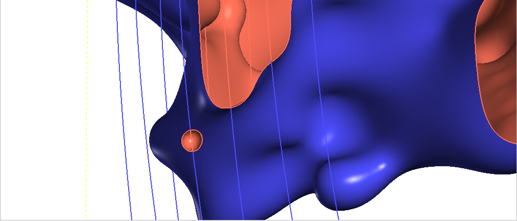
How a polyline can be used to edit a surface can be illustrated by the following surface, where a small volume is disconnected from the main surface:
First, a slice is drawn through the surface where it will be edited:
Next, a polyline is created, using two lines to represent contacts that link up the surfaces:
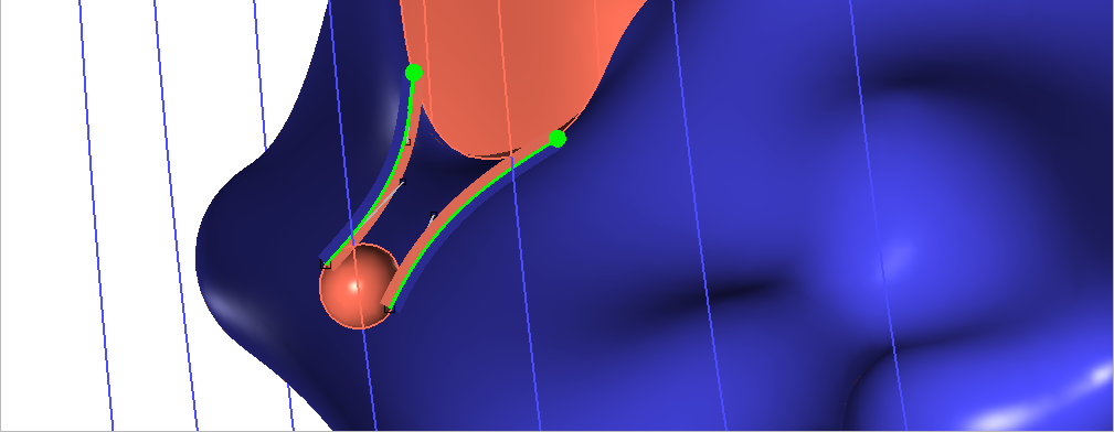
When the polyline edits are saved, the surface is updated to reflect the edits:
It is best to keep polyline edits to a minimum, as small edits can have significant effects on the shapes of surfaces.
If editing a surface with a polyline results in a distorted surface, use the surface and normal ribbons to check the orientation of the polyline and its segments. See Tangents and Ribbons for more information.
When you save the polyline, the object will be updated to reflect the additional points. The polyline will be added to the project tree as part of the object that was edited. You can edit the polyline by double-clicking on it or by right-clicking and selecting Edit Polyline.
Editing Surfaces With Structural Data
In Leapfrog Geo, many surfaces can be edited using planar structural data points drawn in the scene. Surfaces that can be edited in this way include contact surfaces, model extents and interpolated editable meshes. There are two ways to do this:
- If you have a structural data table created in or imported into Leapfrog Geo that you want to use to adjust the surface, right-click on the surface in the project tree and select Add > Structural Data. You will be prompted to select from the structural data tables available in the project.
- If you want to create structural data points to use to adjust the surface, right-click on the surface in the project tree and select Edit > With Structural Data.
To edit a surface with structural data using the second option, it is a good idea to first add the object you wish to edit to the scene. Next, right-click on the surface in the project tree and select the Edit > With Structural Data option.
The structural data toolbar will appear and a new structural data object will be added to the scene. Draw the structural data points and adjust them as described in Creating New Planar Structural Data Tables, then click the Save button (![]() ) to view the effect on the surface. Structural data tables created in this way cannot be used by other objects in the project until the table has been shared. To do this, right-click on the table in the project tree and select Share. The structural data table will be saved to the Structural Modelling folder.
) to view the effect on the surface. Structural data tables created in this way cannot be used by other objects in the project until the table has been shared. To do this, right-click on the table in the project tree and select Share. The structural data table will be saved to the Structural Modelling folder.
To remove the structural data from the surface, expand the surface in the project tree. Right-click on the structural data object and select Remove.
Modifying Surfaces With Anisotropic Trends
More detailed information on Global Trends can be found in the Trends and Anisotropy topic.
How the moving plane can be used to adjust a surface in this manner is illustrated by the following intrusive contact surface:
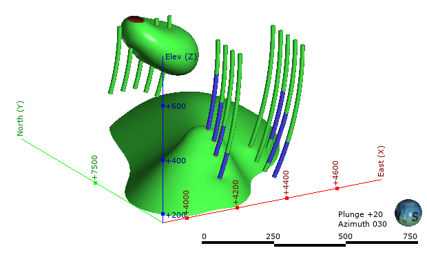
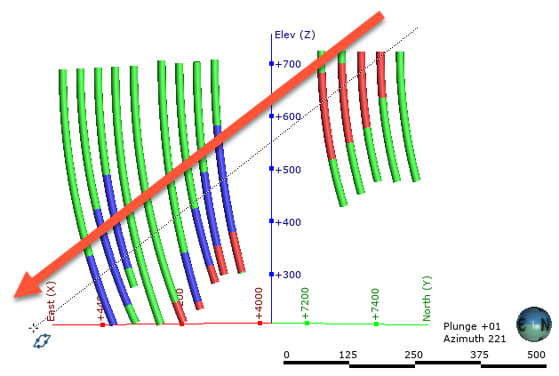
The intrusion surface has two bodies that are not connected, and we can apply a trend to connect the two parts. Here, the intrusion surface has been hidden in the scene and the scene rotated to line up the QzP segments. A plane line can then be drawn through the QzP segments:
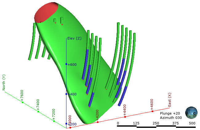
Using the plane settings to adjust the surface results in the two parts of the intrusion joining up:
Applying a Structural Trend
More detailed information on Structural Trends can be found in the Trends and Anisotropy topic.
To apply a structural trend to an interpolated editable mesh or an interpolant, double-click on the object in the project tree and click on the Trend tab:
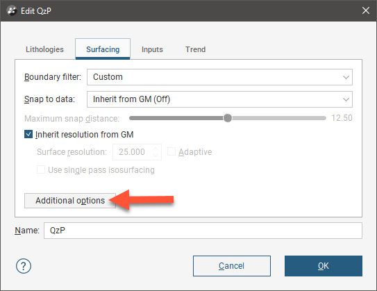
To apply a structural trend to an intrusion contact surface, enable Show additional surfacing options in the Surfacing tab, then click on the Trend tab:
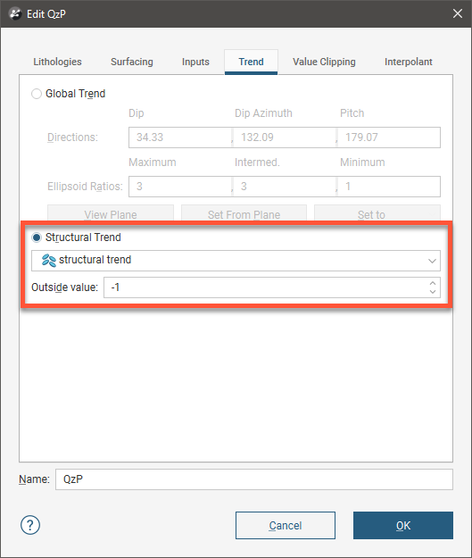
Click on Structural Trend, then select the required trend from the list. Click OK to apply the trend to the surface.
When a structural trend is applied, surfaces may appear distorted further away from the data:
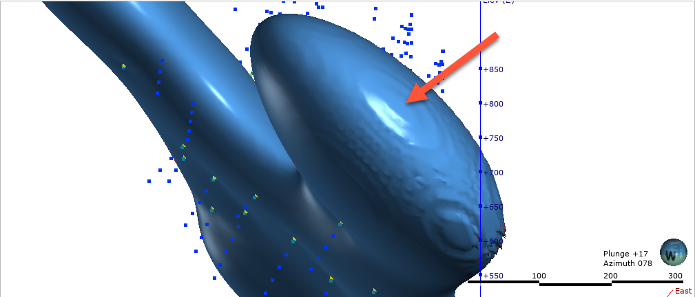
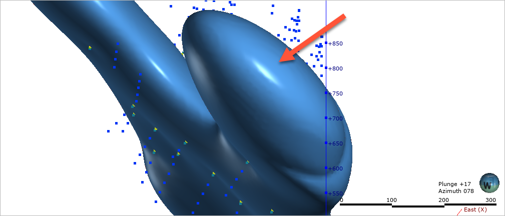
If this is the case, experiment with the Outside value setting. The Outside value is the long-range mean value of the data. Setting a value of -1 for intrusions (where the positive values are on the inside) and +1 for other surfaces will result in a smoother surface in most cases. For example, here, the Outside value has been set to -1 for this intrusion, resulting in a much smoother surface:
Got a question? Visit the Seequent forums or Seequent support