Inverse Distance Weighted (IDW) Grid Interpolants
This feature requires the Geophysics extension.
Whereas RBF interpolants are suited to irregularly-spaced sparse data, an inverse distance weighted (IDW) interpolant is useful in generating isosurfaces and volumes from larger data sets, such as regular or semi-regular grids. An IDW interpolant interpolates points by taking an average of up to eight nearby samples, weighted by distance.
In Leapfrog Geo, you can create an IDW interpolant from gridded geophysical data such as Magnetotelluric models, UBC grids and GOCAD models.
The rest of this topic describes how to create and modify IDW interpolants. It is divided into:
- Creating an IDW Interpolant
- The IDW Interpolant in the Project Tree
- Interpolant Display
- IDW Interpolant Statistics
- Modifying an IDW Interpolant’s Boundary with Lateral Extents
- Changing the Settings for an IDW Interpolant
Creating an IDW Interpolant
To create an IDW interpolant, right-click on the Numeric Models folder and select New IDW Grid Interpolant. The New Inverse Distance Weighted Grid Interpolant window will be displayed:
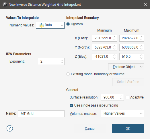
This window is divided into four parts that determine the values used to create the interpolant, the IDW parameters, the interpolant boundary and general interpolant properties.
If you are unsure of some settings, most can be changed later. However, the Numeric values object selected when the interpolant is created cannot be changed.
Values Used
You can build an IDW interpolant from Magnetotelluric models, UBC grids and GOCAD models. All suitable data in the project is available from the Numeric values list.
IDW Parameters
The Exponent setting adjusts the strength of the weighting as distance increases. A higher exponent will result in a weaker weight for the same distance.
The Interpolant Boundary
There are several ways to set the Interpolant Boundary:
- Enter values to set a Custom boundary.
- Use the controls in the scene to set the Custom boundary dimensions.
- Select another object in the project from the Enclose Object list, which could be the numeric values object being interpolated. The extents for that object will be used as the basis for the Custom boundary dimensions.
- Select another object in the project to use as the Interpolant Boundary. Click the Existing model boundary or volume option and select the required object from the list.
Once the interpolant has been created, you can further modify its boundary. See Modifying an IDW Interpolant’s Boundary with Lateral Extents and Adjusting the Interpolant Boundary below.
General Interpolant Properties
Set the Surface resolution for the interpolant and whether or not the resolution is adaptive. See Surface Resolution in Leapfrog Geo for more information on the effects of these settings. The resolution can be changed once the interpolant has been created, so setting a value in the New Inverse Distance Weighted Grid Interpolant window is not vital. A lower value will produce more detail, but calculations will take longer.
The Volumes enclose option determines whether the interpolant volumes enclose Higher Values, Lower Values or Intervals. Again, this option can be changed once the interpolant has been created.
Enter a Name for the new interpolant and click OK.
Once you have created an IDW interpolant, you can adjust its properties by double-clicking on it. You can also double-click on the individual objects that make up the interpolant.
See also:
- Copying a Numeric Model
- Creating a Static Copy of a Numeric Model
- Exporting Numeric Model Volumes and Surfaces
The IDW Interpolant in the Project Tree
The new interpolant will be created and added to the Numeric Models folder. The new interpolant contains objects that represent different parts of the interpolant:
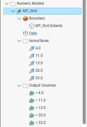
- The Boundary object defines the limits of the interpolant. See Modifying an IDW Interpolant’s Boundary with Lateral Extents.
- The points data values object contains all the data used in generating the interpolant. See Adjusting the Values Used.
- The Isosurfaces folder contains all the meshes generated in building the interpolant.
- The Output Volumes folder contains all the volumes generated in building the interpolant.
Other objects may appear in the project tree under the interpolant as you make changes to it.
Interpolant Display
Display the interpolant by displaying the output volumes or the isosurfaces:
- To view the interpolant’s output volumes, drag the interpolant into the scene or right-click on the interpolant and select View Output Volumes.
- To view the interpolant’s isosurfaces, right-click on the interpolant and select View Isosurfaces.
IDW Interpolant Statistics
You can view the approximated mean for each output volume by right-clicking on the interpolant and selecting Properties. Click on the Statistics tab:
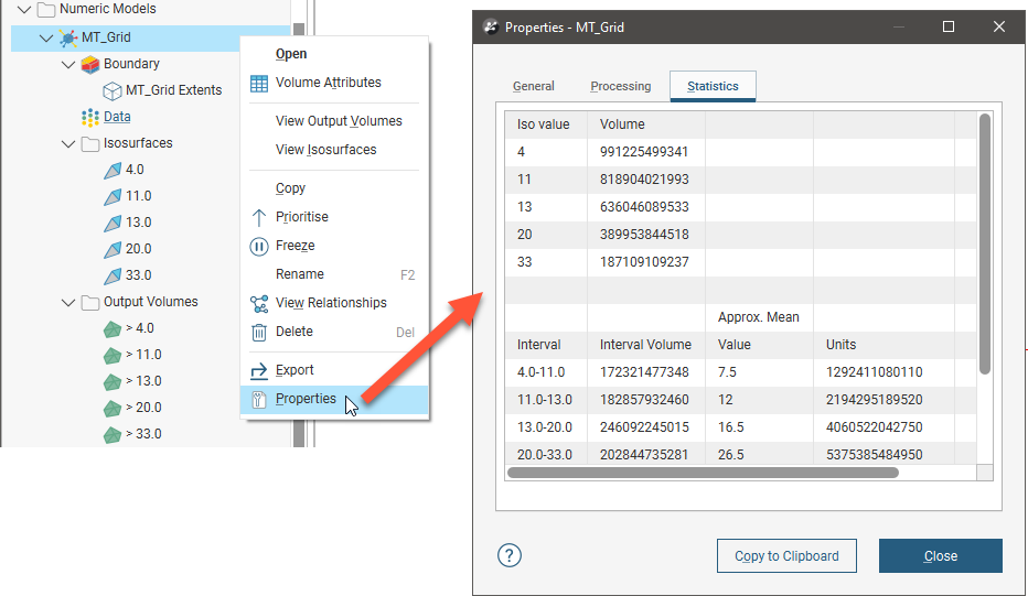
You can copy the information displayed in the Statistics tab to the clipboard for use in other applications.
Modifying an IDW Interpolant’s Boundary with Lateral Extents
IDW interpolants are created with a basic set of rectangular extents that can then be refined using other data in the project. Applying an extent to the interpolant can restrict modelling to a particular region of interest, which will reduce processing time if you are working with a large grid.
To apply an extent, expand the IDW interpolant in the project tree. Right-click on the Boundary object and select from the New Lateral Extent options. Follow the prompts to create the extent, which will then appear in the project tree under the interpolant’s Boundary object.
New extents are automatically applied to the boundary being modified. Leapfrog Geo usually orients a new extent correctly, with red presenting the inside face of the extent and blue representing the outside face. If this is not the case, you can change the orientation by right-clicking on the extent in the project tree and selecting Swap Inside.
See Modifying an RBF Interpolant’s Boundary With Lateral Extents in the RBF Interpolants topic for more information on creating and modifying lateral extents for an IDW interpolant, as the techniques used are the same. Extents for an IDW interpolant can be created from:
- Polylines
- GIS data
- Points data
- Surfaces
- Structural data
- A distance to points
- A distance function
Changing the Settings for an IDW Interpolant
To change the settings for an IDW interpolant, you can either double-click on the interpolant in the Numeric Models folder or right-click and select Open. When creating an IDW interpolant, only a basic set of parameters is used. The Edit Inverse Distance Weighted Grid Interpolant window provides finer controls over these basic parameters so you can refine the interpolant to factor in real-world observations and account for limitations in the data.
The Interpolant tab contains the Exponent setting, which is described in IDW Parameters above.
Adjusting the Interpolant Boundary
See Modifying an RBF Interpolant’s Boundary With Lateral Extents in the RBF Interpolants topic for information on creating and working with lateral extents.
To change an IDW interpolant’s boundary, double-click on the interpolant in the project tree, then click on the Boundary tab:
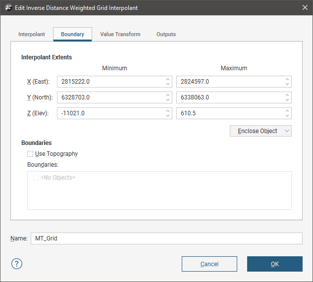
Controls to adjust the boundary will also appear in the scene.
Tick the Use Topography box to use the topography as a boundary. The topography is normally not used as a boundary for interpolants and so this option is disabled when an interpolant is first created.
The Boundaries list shows objects that have been used to modify the boundary. You can disable any of these lateral extents by unticking the box.
Lateral extents can be used to restrict modelling to a particular area of interest; for example, modelling can be restricted to a known distance from drillholes by applying a distance function as a lateral extent.
Clipping and Transforming Values for an IDW Interpolant
To clip data and apply a transformation to an IDW interpolant, double-click on the interpolant in the project tree, then click on the Value Transform tab:
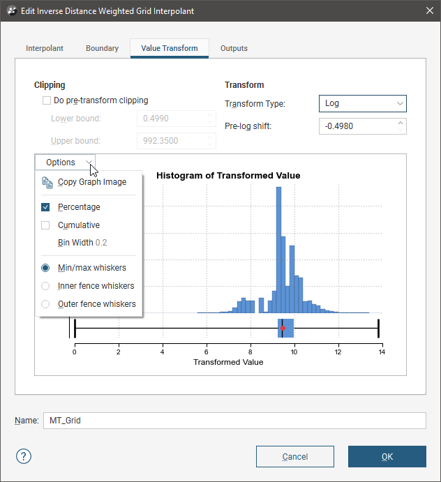
The settings in this tab are the same as those for RBF interpolants. See Clipping and Transforming Values for an RBF Interpolant in the RBF Interpolants topic for more information.
Output Settings for an IDW Interpolant
You can change the parameters used to generate IDW interpolant outputs by double-clicking on the interpolant, then clicking on the Outputs tab.
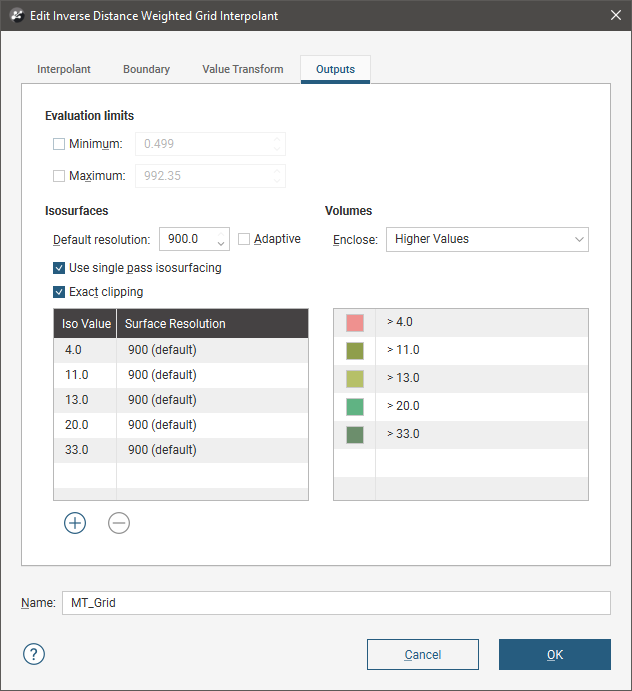
The Evaluation limits apply when interpolants are evaluated against other objects in the project. When the limits are enabled, all values outside the limits will be set to the Minimum and Maximum.
When Exact clipping is enabled, the interpolant isosurface will be generated without “tags” that overhang the interpolant boundary. This setting is enabled by default when you create an interpolant.
To add a new isosurface, click the Add button and enter the required value. To delete an isosurface, click on it in the list, then click the Remove button. You can also change the colours used to display the isosurfaces by clicking on the colour chips.
If you find that grade shells are overlapping, the resolution may be too coarse. Set Default resolution to a lower value or enable adaptive resolution in the Outputs tab. See Surface Resolution in Leapfrog Geo.
Got a question? Visit the Seequent forums or Seequent support
© 2022 Bentley Systems, Incorporated