Settings
Open the Settings window by clicking on the Leapfrog Geo menu and selecting Settings:
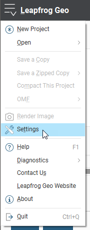
The settings available in this window are described below:
- Display and Navigation Settings
- Overlay Settings
- Colour Scheme
- Lighting Settings
- Processing Settings
- User Interface Settings
- Project Settings
- Usage Policy Settings
- Network Settings
- Coordinate System Settings
To close the Settings window and leave settings unchanged, click the Revert button, then click Close.
Display and Navigation Settings
In the Settings window, click on Scene to change scene display and navigation settings.
3D Acceleration Mode
Leapfrog Geo can run in one of three acceleration modes. Click the Acceleration mode button in the Settings > Scene window to use a different mode. The modes available are:
- Software Rendering uses software only, for maximum compatibility with any hardware. This option can be very slow displaying all but the simplest scenes, and is provided as a fall-back if display issues cannot be resolved with either of the other two options.
- Partial Acceleration uses hardware acceleration that has been provided on graphics cards for many generations. In this mode, Leapfrog Geo renders scenes using “fixed function pipeline” hardware acceleration features that have been superseded in modern graphics cards by programmable shaders, but this legacy capability is widely supported and offers performance advantages over software rendering. Using Partial Acceleration can sometimes fix anomalies or problems encountered in Full Acceleration mode that may be due to bugs in old drivers, and it should work with even old or lower-featured hardware.
- Full Acceleration is the best option, assuming you have good hardware and up-to-date drivers. Because it makes use of programmable shaders provided by modern graphics cards, it is the fastest of the three modes and uses your available graphics memory more efficiently. It is the mode you should use, if your system supports it.
First, try using Full Acceleration and see how it renders scenes. If you seem to be having issues with how data is displayed in the scene, see Running the Graphics Test for information on testing your computer’s graphics capabilities. Note that especially when graphics cards are new on the market, there may be a number of driver versions released to address anomalies, so the use of a recent driver version is important. If using a laptop with dual graphics cards, use it with the power supply connected, and select the Performance Graphics option over the Power Saving option.
If that doesn’t resolve the graphics problems, then try Partial Acceleration mode. If possible, avoid using Software Rendering as it can be very slow.
If your current hardware is unable to support Full Acceleration mode, it may be worth considering upgrading your graphics card. Medium- to high-end home PC and gaming graphics cards are sufficient. High-end workstation grade cards also work very well, but you will also be paying for further capabilities that are not utilised by Leapfrog Geo.
The acceleration mode can also be changed by clicking the button at the bottom of the Leapfrog Geo main window:

Font Size
This setting is the size of text used to display information on the grid and axes.
Z Axis Scale
The Z-axis scale setting lets you set a value greater than 1.0 for the z-axis relative to the x- and y-axes. This is useful when the area under study is very planar and extends over a wide area. In such cases, scaling the z-axis can accentuate the distribution of data along the z-axis. If you have a project open when you change this setting, the change will be reflected in the scene so you can experiment with different values before choosing the one that best accentuates the distribution of data.
The z-axis setting can also be changed by clicking the Z-Scale button at the bottom of the Leapfrog Geo main window. The Scale Z Axis window will appear:
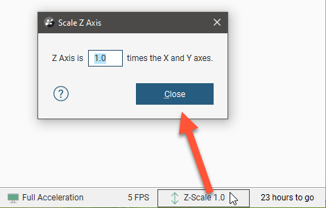
Note that each project saves the z-axis scaling setting when the project is closed. In addition, when saving scenes (see Saved Scenes), the z-axis scale is saved as part of the scene.
Rotation Settings
The Geographic rotation and Free rotation settings determine whether or not the model displayed in the scene window can be “rolled”. With the Geographic rotation option, the azimuth and elevation can be varied, but the z-axis is constrained to be vertical. With the Free rotation option, however, the rotation of the model is not fixed to any axis and the model can be freely rolled around any axis. Select the option you prefer. When Leapfrog Geo is installed, Geographic rotation is set as the default option as it is the most commonly used.
The Rotate with left button and Rotate with right button settings determine how the mouse is used to rotate the scene:
- When Rotate with left button is selected, you can rotate the scene by holding down the left mouse button and dragging in the scene. Clicking and holding the right mouse button zooms in and out of the scene.
- When Rotate with right button is selected, holding down the right mouse button and dragging rotates the scene. However, zooming and rotating functions are not swapped. Instead, the left mouse button can only be used for clicking on different objects in the scene. Select this option if you tend to accidentally move the scene when you intend to click.
Camera Settings
The Orthographic projection and Perspective projection settings determine the view of the model in the scene window.
If Perspective projection is selected, you can change the Perspective angle using the slider. This is similar to adjusting the zoom setting on a camera. Higher angles make nearby objects larger and more distant objects smaller. Lower angles will compress the scene. Experiment with the settings to see the effect on objects in the scene.
Select the option you prefer.
Overlay Settings
In the Settings window, click on Scene > Overlays to change what objects are included in the scene.
Changes you make to these settings are automatically updated in the scene so you can easily experiment to see what overlays you prefer.
Select Revert to return to the settings in place when the Settings window was first opened.
Screen Grid Settings
The Show screen grid setting determines whether or not the screen grid is displayed.
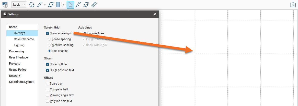
Select the option you prefer. The Loose Spacing, Normal Spacing and Fine Spacing options determine the spacing of the grid.
Axis Lines Settings
The Axis Lines settings determine how X-Y-Z coordinates are displayed in the scene. When axis lines are enabled, the axes indicate the extent of data currently displayed in the scene.
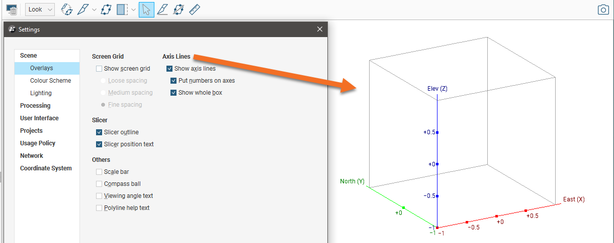
- Enable Show axis lines to display the east (red), north (green) and elevation (blue) axis lines.
- Enable Put numbers on axes to display scale ticks along the grid. These are automatically adjusted to fit the extent of the data and the current zoom setting.
- Enable Show whole box to display the axis lines as a box that encloses the current data set.
Slicer Settings
The Slicer settings determine whether or not additional information about the slicer is displayed when it is in the scene.
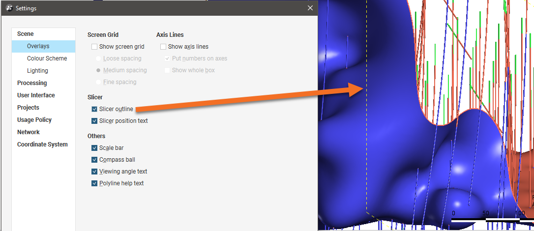
The Slicer outline setting determines whether or not the edges of the slicer are displayed in the scene:
When the slicer is in the scene and the slice is aligned with the x-, y- or z-axis, text describing the slicer position can be displayed in the lower left-hand corner of the scene:

To do this, enable the Slicer position text option.
Other Overlay Settings
The scale bar, compass ball and viewing angle text are the navigation aids in the lower right-hand corner of the scene window:

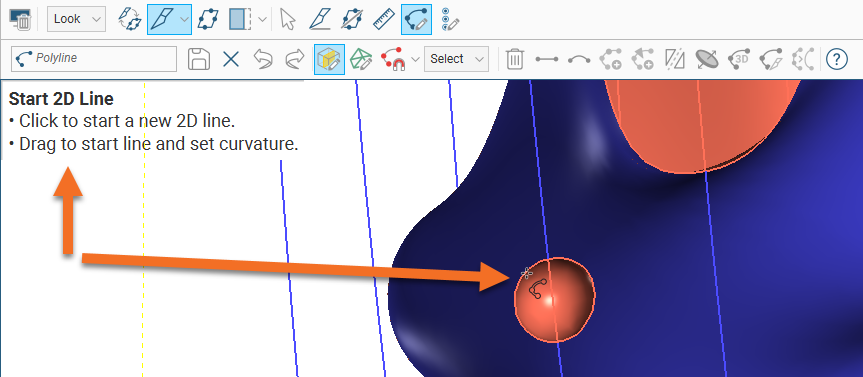
When drawing polylines, tooltips are displayed. If you do not wish to view these tooltips, untick the box for Polyline help text:
Colour Scheme
In the Settings window, click on Scene > Colour Scheme to change the colour scheme used in the 3D scene. The options that can be changed include:
- The background colour used in the Scene View tab
- The colour and width used to display drillhole traces
- The colour and width of mesh edges, together with the width of the line used when a mesh is sliced and the highlight colour used when mesh parts are selected in the scene
- The colours used for displaying the x, y and z axes
- Grid line width, style and colour
- Axes box line width, style and colour
- Slicer edge width, style and colour
Leapfrog Geo is installed with three colours schemes: Default, Black Background and White Background. The scheme selected in the Schemes list will be used for all new Leapfrog Geo projects and for existing projects when they are next opened.
- Experiment with the settings to see how they affect the scene window. The scene will be updated as you make changes.
- Select Revert to return to the settings in place when the Settings window was first opened.
- To create a new scheme, click on an existing scheme. This is the scheme that will be used as a basis for defining the new scheme. Next, click the Add button (
 ) and change its settings.
 - Click Reset to revert to the colour schemes defined when Leapfrog Geo was first installed.
Clicking on Reset to revert to the original colour schemes deletes any custom colour schemes.
Lighting Settings
In the Settings window, click on Scene > Lighting to change how visual effects are displayed in the scene window. You may be able to use these settings to emphasise significance in the data displayed in the scene.
- The Ambient level setting determines the overall brightness of the scene.
- The Specular brightness and Specular shininess settings determine how light appears to fall on the surfaces in the scene. The Specular brightness setting has a stronger effect when Specular shininess is soft.
You can have up to four light sources defined for a project. By default, two light sources are defined.
Changes made to these settings are automatically applied to the scene.
- Click Revert to return to the settings in place when the Settings window was first opened.
- Click Reset to revert to the lighting sources and settings defined when Leapfrog Geo was first installed.
Processing Settings
In the Settings window, click on Processing to change how background processing is used to run changes to data and models. The Automatic option creates one process for each physical CPU core on your computer or one for every 2.5 GB of RAM, whichever is smaller. However, there is an upper limit of 8 processes.
You can manually set the number of Background processes you would like to commit resources to. For example, you might want to use all but one process for Leapfrog Geo and reserve one for other application use.
Select Revert to return to the settings in place when the Settings window was first opened.
User Interface Settings
In the Settings window, click on User Interface to change project tree and scene toolbar options.
Show Tree Lines
Ticking the box for Show Tree Lines displays objects in the project tree with lines:
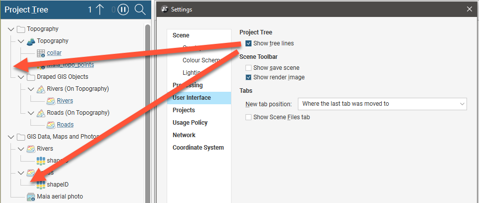
Enable this option if you find it useful for displaying relationships between objects in the project tree.
Show Save Scene Button
Ticking the Show Save Scene box adds an extra button to the scene toolbar:
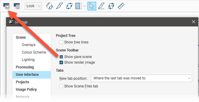
Click this button to save the current scene.
You can also change the scene toolbar by right-clicking on it and selecting Customise.
Show Scene Files Tab
When the Show Scene Files tab option is enabled, a Scene Files tab will be displayed in the main window:

This tab will display scene files, which you can then open, as described in Leapfrog Viewer Integration.
If you do not work with scene files, disable this option.
Tab Position
Some Leapfrog Geo windows open in separate tabs that can be used either docked or detached. The position in which tabs open is determined by the New tab position setting:
- Open all tabs in the main window.
- Open all tabs in separate windows.
- Tabs can open where the last tab was moved to. This setting can be used for creating a window in which all tables and dockable windows open, with the scene window, project tree and shape list in another window.
Project Settings
The settings in the Projects tab relate to where Leapfrog Geo and Central projects are stored on your local hard drive. There are also connection-related parameters that can be adjusted if you have issues downloading from and publishing to Central.
- Local Projects > Default Location. This is the folder on your hard drive that is used for storing local Leapfrog Geo projects, that is, Leapfrog Geo that are not stored on a Central server. If the Use Seequent ID setting is disabled, this option will not appear in the Settings window and is instead set in the Projects tab.
- Central Projects - Local > Default Location. This is the folder on your hard drive that is used for storing local copies of projects that you download from Central.
- Publishing cache. This determines where Central data is stored while publishing to Central. If you have a small local drive and use network storage for most of your data, you can change where temporary publishing data is stored. To do this, click on the Change button and navigate to the required location. The Empty Cache button clears the publishing cache folder for the connected Central Server. This button is only active when you are connected to a Central server and should only be used if you are having problems publishing to Central.
- Default request timeout and Large request timeout. The Large request timeout setting is used for publishing, uploading attachments and getting a revision. All other communication with the Central server uses the Default request timeout. The Default request timeout and Large request timeout should only be adjusted upward if you have problems with a poor connection. The default values are 60 seconds and 600 seconds.
- Upload chunk size. This setting is useful if you have a poor connection. It determines the size of the chunks used to upload large files. For example, if the Upload chunk size is 10MB and you are uploading a 100MB file, the file will be uploaded in 10 chunks. If your connection is poor and you are experiencing issues, you can decrease the value of the Upload chunk size.
- Check file consistency after upload. This setting determines whether the integrity of a revision is checked after it has been published to Central. If you wish to do this, enable the Check file consistency after upload.
Usage Policy Settings
When the Idle time-out setting is enabled, Leapfrog Geo will prompt you after a period of inactivity. Follow the instructions in the message displayed.
Leapfrog Geo can use reference codes to track work on specific projects. The number of days associated with each reference code is included in your organisation’s monthly usage report. In the Settings > Usage Policy window, you can define reference codes on a per-project or per-computer basis. Click the Add New Code button to add a code for either the computer or the currently open project.
The other two settings can be used to ensure that you are regularly prompted to update the reference code.
- Prompt at project start up ensures that a prompt is displayed for selecting a reference code whenever a project is opened or a new project is created.
- Always required ensures that Leapfrog Geo is not used without a reference code being selected; <No Code> is not an option.
Network Settings
If your organisation uses a proxy server to connect to the internet, you can set this up in the Settings > Network window.
If you choose the Autodetect proxy server option, Leapfrog Geo will detect the authentication type, server address and port; there are no further settings for you to change.
If Autodetect proxy server does not work or if you need to switch between proxy servers in different network environments, choose the Manually configure proxy server option and enter the information provided by your IT department. The advanced settings are optional and you should only change them from the default values if you have been instructed to do so by your IT department.
You can manually configure more than one proxy server. Click the New button to add a new profile and enter the required settings. When you want to swap from one proxy server to another, simply select a Profile from those already defined.
If you have multiple Seequent products running on your computer, you only need to configure network proxy settings once.
Coordinate System Settings
In the Settings window, click on Coordinate System to record the coordinate system the team should use when importing data into the currently open Leapfrog Geo project. See Recording a Coordinate System in the Managing Leapfrog Geo Projects topic.
The Projected Coordinate System setting is primarily an informational field. The project coordinate system should be set when the project is created and all the data imported into Leapfrog Geo should use the coordinate system that has been decided on for the project. Leapfrog Geo will not convert any data that is imported with references using a different coordinate system into the project coordinate system, nor does changing the project coordinate system perform a conversion of the data within Leapfrog Geo from the previous coordinate system to the new coordinate system.
Got a question? Visit the Seequent forums or Seequent support
© 2023 Seequent, The Bentley Subsurface Company
Privacy | Terms of Use
