
Veins
A vein is a type of contact surface that removes existing lithologies and replaces them with the vein lithology within the boundaries defined by hangingwall and footwall surfaces constructed from selected input data, a reference surface and a boundary. Creating veins from drilling data provides the most flexibility in refining the vein surface, but veins can also be created from points data, GIS vector data and polylines.
Modelling veins is an iterative process that may involve creating and refining a vein surface using different techniques before arriving at a surface that most accurately reflects sub-surfaces structures. Furthermore, the vein modelling tools available in Leapfrog Geo can be used for modelling other thin, planar geometries.
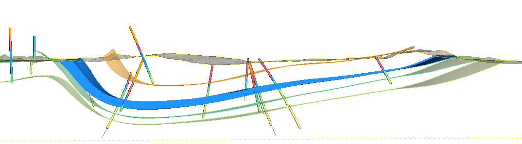
The way vein contact surfaces are organised in the project tree is intended to help you in working with the data available, so it is a good idea to have an understanding of this organisation so you can decide how to work with the different objects that contribute to the final vein surface. Veins are created and stored as part of a geological model’s Surface Chronology. Here, the hangingwall and footwall surfaces (with triangles shown) and points are displayed in the scene for a vein defined from drilling data. The reference surface (yellow) and the vein segments (red and blue cylinders) used to create the vein are also shown:
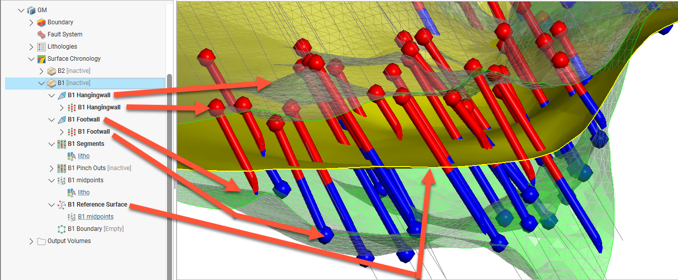
This vein (![]() ) is made up of:
) is made up of:
- Hangingwall and footwall surfaces (
 ). When expanded, you can see the hangingwall and footwall data objects used to create the surfaces. In this example, the vein has been created from drilling contacts and so the hangingwall and footwall have been created from points (
 ).
). - Vein segments (
 ), pinch out segments () and midpoints (
 ) extracted from drilling data. Veins created from data other than drilling data will not have vein segments, pinchout segments or midpoints.
- Vein segments are categorised into hangingwall segments, footwall segments or excluded segments. Excluded segments are those that are completely enclosed within the vein lithology and so do not have hangingwall or footwall contact points.
- Pinch outs are only included when the Pinch out option has been enabled.
- Midpoints are used to create a first-pass reference surface.
- A reference surface (
 ) representing the trend or form of the vein. When a vein is created from drilling data, the initial reference surface is calculated as the best fit surface using the midpoints and the hangingwall and footwall surfaces. For veins created from data other than drilling data, the initial reference surface is a planar reference surface.
 - A boundary object (
 ). This is empty when the vein is first created.
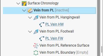
If the vein is created from data other than drilling data, that data will be linked to from the hangingwall and footwall surfaces. For example, this vein was created from polylines. Note that there are no vein segments, pinchout segments or midpoints to work with.
Vein contact surfaces can also be created as part of a vein system (![]() ), in which case, each vein (
), in which case, each vein (![]() ) is linked to the vein system via a “terminated vein” (
) is linked to the vein system via a “terminated vein” (![]() ) that takes into account the vein’s relationship to other veins in the vein system. For example, in this vein system, a series of terminated veins make up the system. Expanding a terminated vein shows the vein surface (
) that takes into account the vein’s relationship to other veins in the vein system. For example, in this vein system, a series of terminated veins make up the system. Expanding a terminated vein shows the vein surface (![]() ) and any interactions with other veins in the vein system. Here vein 4501 interacts with vein 4400 on its hangingwall side, and so vein 4400’s hangingwall side is hyperlinked to vein 4501.
) and any interactions with other veins in the vein system. Here vein 4501 interacts with vein 4400 on its hangingwall side, and so vein 4400’s hangingwall side is hyperlinked to vein 4501.
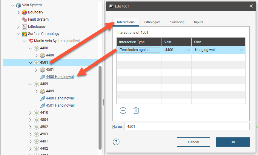
Vein 4409 interacts with two other veins, 4400 and 4501, and so contains hyperlinks to those veins:

Working with vein systems is described in the Vein Systems topic.
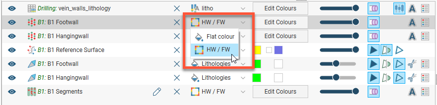
Displaying the different objects that make up the vein can help you in making decisions on how to edit the vein. There are some settings specific to veins, such as the option for displaying different vein components by their hangingwall/footwall assignments:
The rest of this topic describes how to create and work with veins. It is divided into:
- Creating Veins
- Copying Veins
- Vein Surfacing Settings
- Pinch Outs
- Vein Segment Settings
- Editing Vein Segment Orientations
- Editing Vein Midpoints
- Editing the Reference Surface
- Editing the Vein Boundary
- Exporting and Importing Pinchout, Segment and Midpoint Edits
For a general introduction to how veins interact with other contact surfaces, see Vein Contact Surfaces in the Building Surfaces Using the Surface Chronology topic.
Creating Veins
Options for creating veins are:
- From the geological model's base lithology data. See New Vein From Base Lithology below.
- From other lithology contacts available in the project, including those from other drilling data sets. See New Vein From Other Contacts below.
- From GIS vector data, point data and polylines. See Veins From Other Data below.
- Creating a vein system. This results in a single lithology that represents all the veins in a model. Veins and their interactions are defined within the vein system. See Vein Systems.
New Vein From Base Lithology
To create a new vein from base lithology contacts, right-click on the Surface Chronology object and select New Vein > From Base Lithology. In the New Vein window, select the Vein lithology.

The options available are only those lithology codes in the base lithology column; codes manually added to Lithologies in the geological model are not available.
You can choose to use the query filtering already selected for the geological model by ticking the Inherit from GM box, or untick it and select from the available options in Query filter.
Click OK to create the vein, which will be added to the project tree as part of the Surface Chronology object.
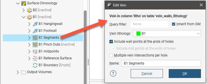
The Include wall points at the ends of holes, Include mid points at the ends of holes and Multiple vein intersections per hole settings are discussed later in this topic, in Vein Segment Settings. To change the settings in this window for an existing vein, expand the vein in the project tree and double-click on the vein segments (![]() ):
):
New Vein From Other Contacts
When a vein is to be created using a lithology column other than the geological model’s base lithology column, right-click on the Surface Chronology object and select New Vein > From Other Contacts.
In the New Vein Contact window under Select Data, click the Select button and choose the column containing the needed lithology information.
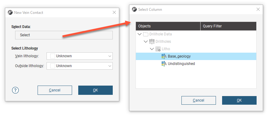
Once a data column has been selected, the rest of the New Vein Contact window can be completed. Note that both the Vein lithology and Outside lithology fields draw their options from the geological model's Lithologies codes, not the codes from the column just selected. Selection of the lithology data to be used in construction of the vein happens in the next step. Here the Vein lithology field is asking which of the Lithologies in the geological model will be used to represent the data being introduced from the other contacts. If no code in Lithologies is appropriate, manually add a new code, as described in Geological Model Lithologies.
If the vein contacts only one lithology, set the Outside lithology. Otherwise, leave Outside lithology set to Unknown.

After you click OK in the New Vein Contact window, the New Vein window will appear. The Vein lithology option in this window is used to specify the lithology code from the selected column that will be used to construct and model the vein. In this illustrated example, a geological model has been constructed from the Undistinguished column, and a new vein is being defined using other contacts contained in the Base_geology column. Therefore, the options showing in this Vein lithology are the codes from the Base_geology column, not the Undistinguished column nor the geological model's Lithologies.

The other fields in the New Vein window are as described in New Vein From Base Lithology.
Veins From Other Data
If suitable lithology data is not available, veins can be created from other data in the project, either GIS vector data, points or polylines. The steps for creating veins from other data are similar, regardless of the data used to create the surface:
- Right-click on the Surface Chronology, select New Vein, then select one of:
- From Polylines
- From GIS Vector Data
- From Points
- Select the data objects for the Hangingwall and Footwall. These objects must already be in the project.
- Select the Vein lithology and the Outside lithology. The lithologies you can choose from are those defined for the geological model in the Lithologies object (see Geological Model Lithologies).
Here, a points table is being used to create a vein:

Select data objects for both the Hangingwall and Footwall, then select lithologies. The Vein lithology and Outside lithology fields draw their options from the geological model's Lithologies codes.
- The Vein lithology field is asking which of the Lithologies in the geological model will be used to represent the data being introduced from the polylines, GIS data, or points. If no code in Lithologies is appropriate, manually add a new code, as described in Geological Model Lithologies.
- If the vein contacts only one lithology, set the Outside lithology. Otherwise, leave Outside lithology set to Unknown.
Click OK to create the new vein. The new contact surface will appear in the project tree under the Surface Chronology. Expand the vein in the project tree to see how it was made.
Copying Veins
As described in Copying Contact Surfaces in the Building Surfaces Using the Surface Chronology topic, you can copy veins and vein systems, which is useful in experimenting with the effects of different settings and in ensuring the consistency of settings across surfaces.
It is also possible to copy individual veins into and out of vein systems.
To copy a single vein into a vein system, right-click on a vein system and select Copy Vein from Chronology. Select from the available veins:
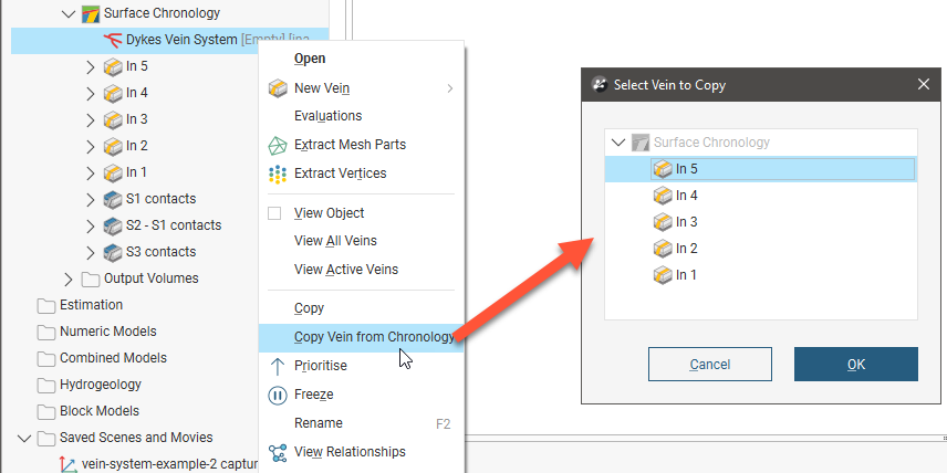
You can also drag a vein into a vein system. Here the vein In1 is being dragged into to the Dykes Vein System:

When you drop a vein into a vein system, a duplicate copy of the vein will be made and added to the vein system, while the original single vein remains:

To move a vein out of a vein system, drag it onto the surface chronology:

A copy will be made in the top level of the surface chronology, while the original vein remains in the vein system:

Vein Surfacing Settings
Double-click on a vein in the project tree to edit its lithologies and various surfacing settings.
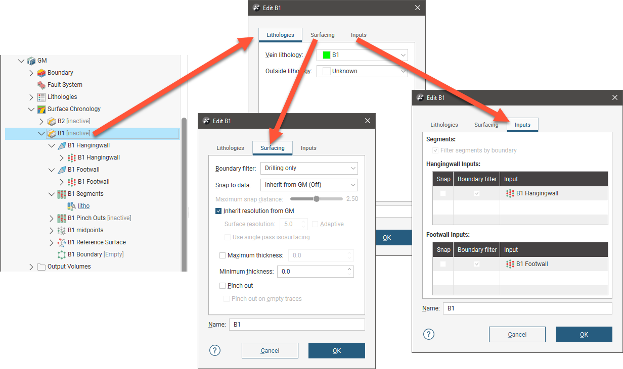
- The only settings you can change in the Lithologies tab are the Vein lithology and the Outside lithology.
- The options in the Surfacing tab are discussed below.
- The Inputs tab contains additional settings related to the boundary filtering and snap settings in the Surfacing tab.
Settings such as surface resolution, boundary filtering and snapping can be set for the model as a whole but these can also be set on a surface-by-surface basis.
See the Creating and Editing a Geological Model topic for information on these settings for the overall geological model.
Each contact surface in a model has a Surfacing tab in which you can customise its surface resolution, boundary filtering and snapping settings. There are additional settings related to boundary filtering and snapping to data in the Inputs tab.
Boundary Filtering
When data objects are added to a surface, there are two ways to handle the data that lies outside the surface’s boundary:
- Filter the data. The surface is only influenced by the data that falls inside the surface’s boundary.
- Leave the data unfiltered. The surface is influenced by the data both inside and outside the surface’s boundary.
The boundary of a vein can be the geological model boundary or a fault block boundary.
The Boundary filter setting determines how data used to define the surface is filtered:
- Inherit from GM. The setting for the geological model as a whole is used. This is the default setting.
- Off. Data is not filtered.
- All data. All data is filtered.
- Drilling only. Only drilling data and data objects derived from drilling data are filtered.
- Custom. Only the data objects specified in the Inputs tab are filtered.
The Filter segments by boundary setting in the Inputs tab is enabled by default when the Boundary filter setting in the Surfacing tab is All data or Drilling only. When Filter segments by boundary is enabled, the vein surface will only be influenced by the segments that falls inside the vein boundary.
Snapping to Data
Often, surfaces should honour drilling data and treat data objects such as polylines and GIS data as interpretations. See Honouring Surface Contacts in the Modifying Surfaces topic.
There is a Snap to data setting for a geological model as a whole that is set in the Geological Model > General tab (see Creating and Editing a Geological Model). Snap to data can also be set on a surface-by-surface basis by double-clicking on the surface in the project tree and then clicking on the Surfacing tab.
For individual contact surfaces, the options are:
- Inherit from GM. The setting for the geological model as a whole is used. This is the default setting.
- Off. Surfaces do not snap to the data used to create them.
- All data. Surfaces snap to all data within the Maximum snap distance, which includes drilling data and any data added to the surfaces.
- Drilling only. Surfaces snap to drilling data and data objects derived from drilling data within the Maximum snap distance but not to other data used to modify the surfaces.
- Custom. Surfaces snap to the data objects indicated in the Inputs tab for each surface.
Take care in enabling snapping and in selecting what data the surface will snap to, as the more data you include, e.g. by setting a large Maximum snap distance or selecting All data for Snap to data, the greater the possibility that errors in the data or assumptions inherent in interpretations (e.g. polylines) will cause distortions in the meshes. If you do enable snapping, it is best to snap only to drilling data. See Honouring Surface Contacts in the Modifying Surfaces topic for more information on these settings.
If you need a surface to honour drilling data but treat other data objects as interpretations, select Drilling only. To honour some data objects while treating others as interpretations, select Custom, then click on the Inputs tab to enable snapping for individual objects.
Surface Resolution
See Surface Resolution for a Geological Model for information about the surface resolution settings for veins.
Adaptive surfacing for veins was introduced in Leapfrog Geo 2021.1. When existing geological models with veins are upgraded in Leapfrog Geo 2021.1 or later, the Adaptive setting will be disabled. If the vein is set to inherit its resolution from the geological model and the geological model has been set to use adaptive resolution, the Inherit resolution from GM setting will be disabled so that the vein’s previous settings are preserved.
Vein Thickness
Veins have two thickness settings that force the vein to maintain a minimum or maximum thickness. If footwall and hangingwall points are in pairs, it is not usually necessary to set the Minimum thickness or Maximum thickness.
- If the vein intersects itself, set the Minimum thickness to a value that is less than the minimum distance between any two contact points.
- If the vein widens out toward the edges of the geological model set the Maximum thickness to a value that limits the effects of long segments.
If the Pinch out option is enabled, you will not be able to set the Minimum thickness.
If you set the Maximum thickness and Pinch out, the Pinch out setting is applied before the Maximum thickness.
Note that if Snap to data is enabled, snapping occurs after the vein thickness has been calculated. If it appears that the vein surface is not honouring the thickness setting, check what data the surface is snapping to.
Pinch Outs
Vein walls can be set to pinch out where drilling data indicates they do not occur. This is achieved by creating ‘outside’ intervals on drillholes that do not have an interior vein segment. These intervals are then flipped with respect to interior vein intervals, which, in effect means the footwall and hangingwall orientation has the opposite sense to the nearest interior intervals. This forces the hangingwall and footwall surfaces to cross, thereby pinching out.
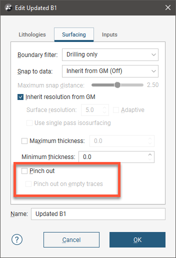
The Pinch out option is disabled when a vein is first created. To enable it, double-click on the vein in the project tree and click on the Surfacing tab. Tick the box for Pinch out:
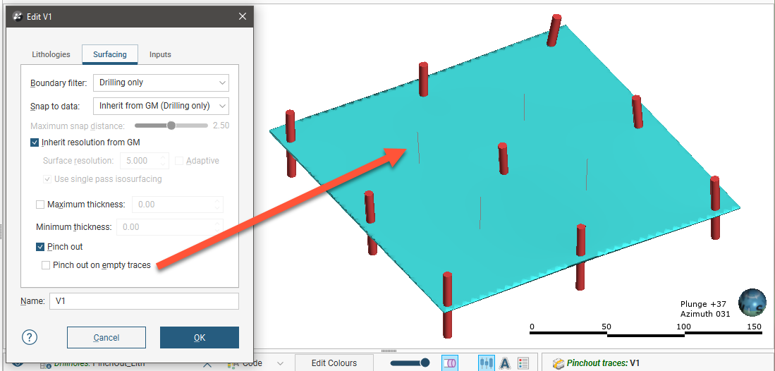
When the Pinchout on empty traces option is enabled, pinchouts will be created on drillhole traces that have no logged data. To illustrate the effect of this setting, we have an artificial data set that has four traces with no logged data. When Pinchout on empty traces is disabled, the vein does not pinch out where it appears there are no actual vein segments:
When the option is enabled, however, the vein pinches out around the empty traces:

Click OK to process the changes.
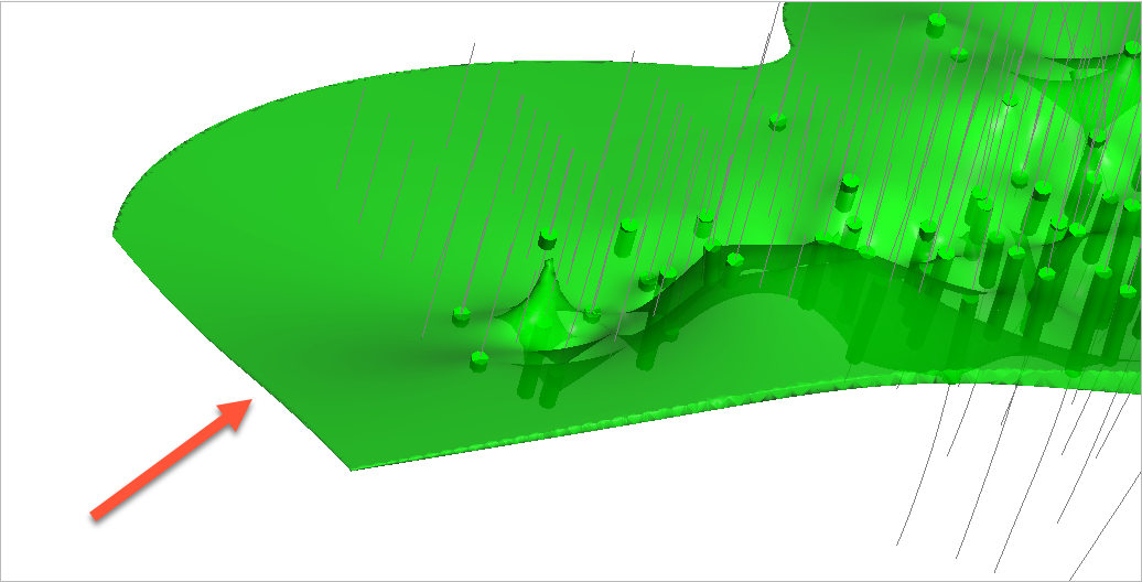
For this vein, the surface occurs even where the vein lithology (green cylinders) does not occur and terminates at the boundary of the geological model:
When the vein is set to pinch out, it tapers out where the vein lithology does not occur:

You can change how much the vein pinches out by manually excluding some pinch out segments. To do this, right-click on the pinch out segments (![]() ) in the project tree and select Edit in Scene:
) in the project tree and select Edit in Scene:

If you manually edit pinchouts, you can export the edits for use in other veins and models in the current project or in other projects. The edits are exported in a text file. See Exporting and Importing Pinchout, Segment and Midpoint Edits for more information.
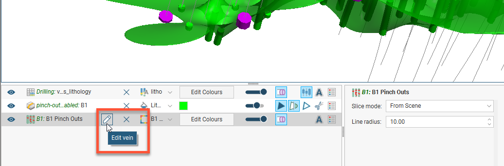
You can also add the pinch out segments to the scene and click the Edit button (![]() ) in the shape list:
) in the shape list:
The Vein Pinchout Segments will appear, along with a set of tools for selecting segments in the scene:
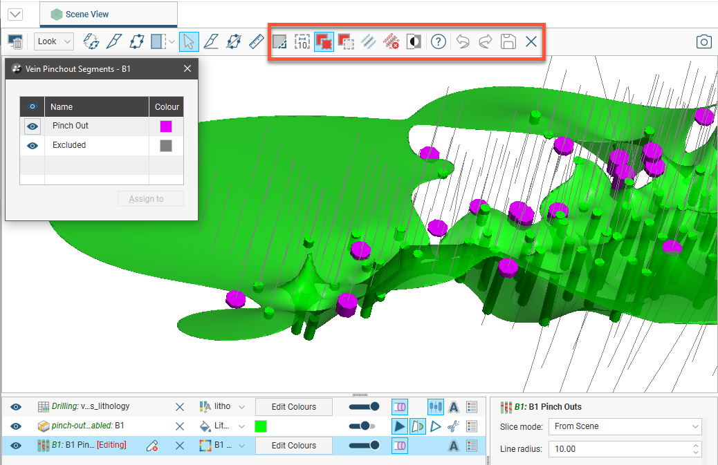
To select segments, click on the Select segments button (![]() ) and click the Add segments button (
) and click the Add segments button (![]() ). In the scene, draw a line across each segment you wish to select:
). In the scene, draw a line across each segment you wish to select:

Note that the segments displayed in the scene below are the pinch out segments rather than the drillhole segments shown in earlier scenes. The grey segments are excluded and the currently selected segment is highlighted in the scene.
Selected segments are highlighted in the scene. If you accidentally select the wrong segment, either:
- Click the Remove segments tool (
 ) and draw across the point once again.
 - Hold the Ctrl key while drawing across the point.
You can also:
- Select all visible segments by clicking on the Select all tool (
 ) or by pressing Ctrl+A.
 - Clear all selected segments by clicking on the Clear selection tool (
 ) or by pressing Ctrl+Shift+A.
 - Swap the selected segments for the unselected segments by clicking on the Invert selection tool (
 ) or by pressing Ctrl+I.
To change the width of the line used to select segments, click on the Change line width button (![]() ) and enter a new value. You can keep the Set Line Width window open while you select intervals so you can change the line width as required:
) and enter a new value. You can keep the Set Line Width window open while you select intervals so you can change the line width as required:

Note that the current line width is indicated by the Change line width button.
When you have selected at least one segment, click on the Assign to button, then select the category you want to assign the selected segments to:
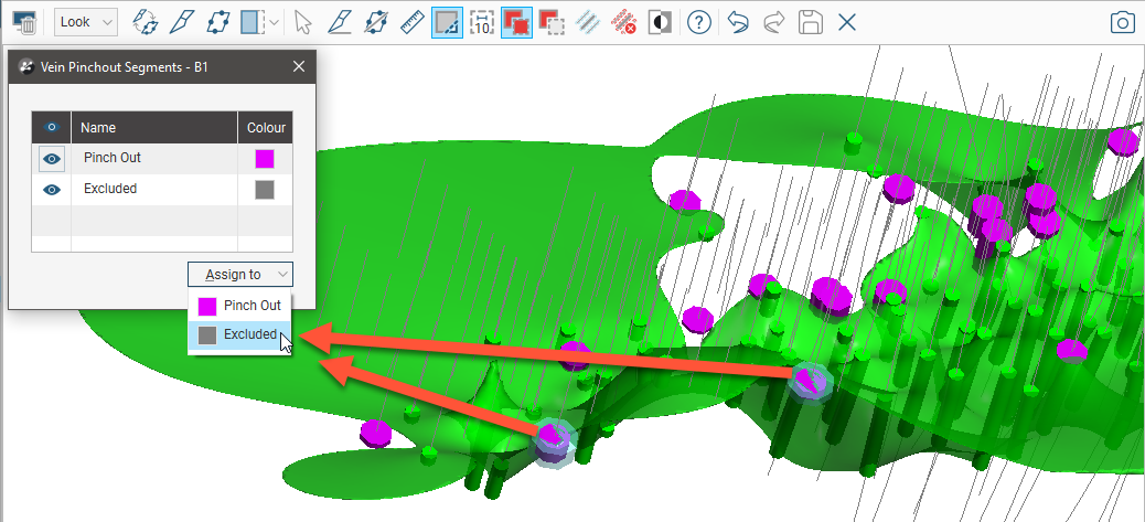
The selected segments will be updated to reflect the change:
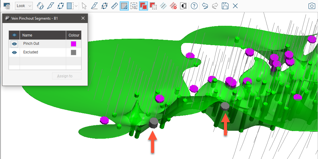
Click the Save button (![]() ) to view the effect of the excluded pinch out segments on the vein. In this example, excluding the two segments results in the vein terminating at the boundary of the geological model:
) to view the effect of the excluded pinch out segments on the vein. In this example, excluding the two segments results in the vein terminating at the boundary of the geological model:

Vein Segment Settings
When a vein has been created from contact points, you can change the vein segment settings by double-clicking on the vein segments object (![]() ) in the project tree. This opens the Edit Vein window:
) in the project tree. This opens the Edit Vein window:
Settings in this window that change how contact points are generated from lithology data are:
Include Wall Points/Midpoints at Ends of Holes
The Include wall points at the ends of holes setting determines whether or not hangingwall and footwall contact points are generated for segments at the ends of drillholes. If this setting is disabled, a contact point will not be created when a drillhole ends in the vein lithology. The related setting, Include mid points at the ends of holes, determines whether or not midpoints are generated for segments at the ends of drillholes. Such midpoints could be distant from the centre of the vein structure and would, therefore, result in localised distortion of the reference plane.
You can see the effects of the Include wall points at the ends of holes setting here where the hangingwall (red) and footwall (blue) points are displayed alongside the vein lithology intervals (in yellow), the drillhole traces and the resulting vein surface. In the first example, Include wall points at the ends of holes is disabled. Hangingwall points are not generated at the ends of the drillholes where indicated and so there isn’t enough data to build the vein surface:
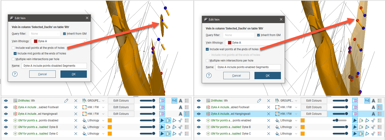
In the second example, Include wall points at the ends of holes is enabled, hangingwall contact points are created and the vein surface that results is much more realistic.
Whether to enable or disable Include wall points at the ends of holes depends on your data. Consider disabling Include wall points at the ends of holes if:
- A vein is being prematurely truncated
- A vein is blowing out unrealistically
The Include mid points at the ends of holes affects how the midpoints are generated when vein lithology segments occur at the start or end of drillholes. When Include mid points at the ends of holes is disabled, the midpoints are still generated but are automatically excluded. In these examples, there are three segments where drillholes end with the vein lithology. On the left, Include mid points at the ends of holes is enabled and there are no excluded midpoints; all the midpoints are shown in green.

On the right, midpoints at the ends of holes are not included and so are shown in grey (Excluded).
Consider disabling the Include mid points at the ends of holes setting if your reference surface is “wiggly” or otherwise showing unexpected distortions.
To change the settings in this window for an existing vein, expand the vein in the project tree and double-click on the vein segments (![]() ):
):
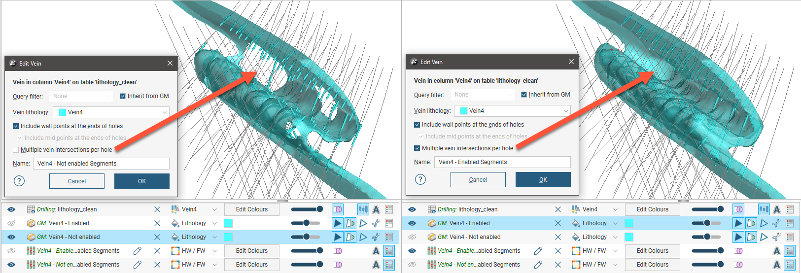
Multiple Vein Intersections Per Hole
The Multiple vein intersections per hole setting is useful situations where drillholes might pass in and out of the same vein unit multiple times. Here a folded vein is shown with Multiple vein intersections per hole disabled (left) and enabled (right):
Note that you may also need to edit the vein’s reference surface and the vein segments to achieve a realistic surface. See Editing the Reference Surface and Editing Vein Segment Orientations below.
Editing Vein Segment Orientations
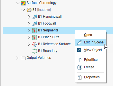
If you need to change the orientation of individual vein segments, e.g. for curved veins, you can do this by right-clicking on the vein segments object (![]() ) in the project tree and selecting Edit In Scene.
) in the project tree and selecting Edit In Scene.
If you manually edit vein segments, you can export the edits for use in other veins and models in the current project or in other projects. The edits are exported in a text file. See Exporting and Importing Pinchout, Segment and Midpoint Edits for more information.
If the vein segments object is already in the scene, you can edit it by clicking the Edit button (![]() ) in the shape list:
) in the shape list:

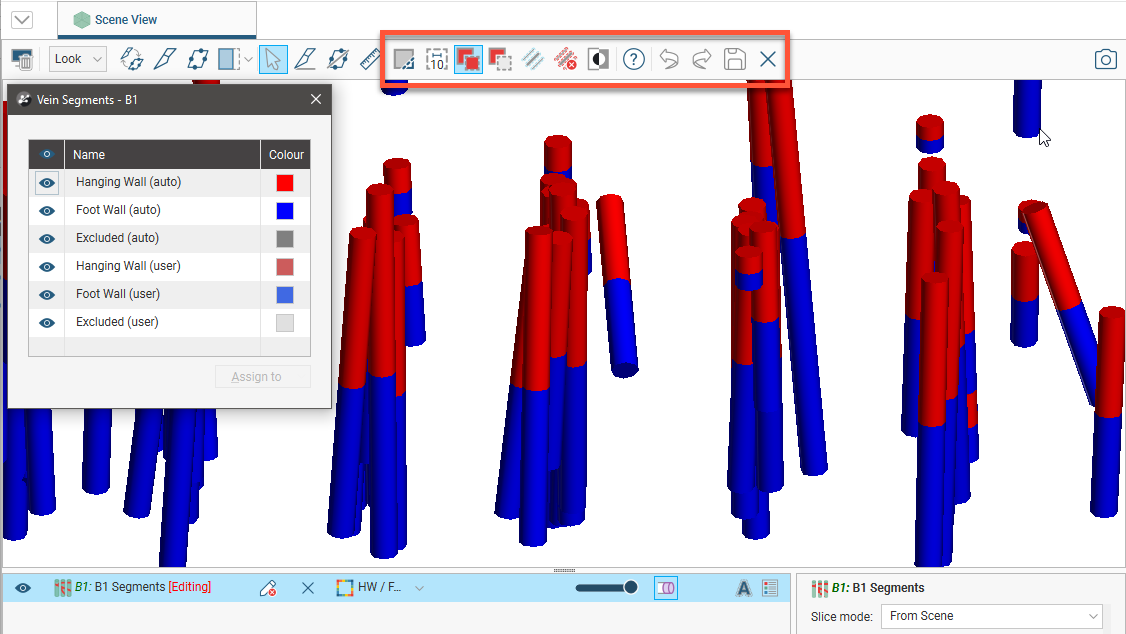
Vein segments are categorised into hangingwall segments, footwall segments or excluded segments. Excluded segments are those that are completely enclosed within the vein lithology and so do not have hangingwall or footwall contact points.
The Vein Segments window will appear, along with a set of tools for selecting segments in the scene:
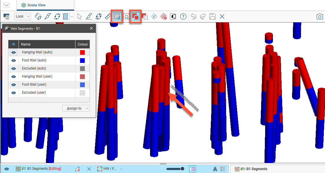
To select segments, click on the Select segments button (![]() ) and click the Add segments button (
) and click the Add segments button (![]() ). In the scene, draw a line across each segment you wish to select:
). In the scene, draw a line across each segment you wish to select:
Selected segments are highlighted in the scene. If you accidentally select the wrong segment, either:
- Click the Remove segments tool () and draw across the point once again.
- Hold the Ctrl key while drawing across the point.
You can also:
- Select all visible segments by clicking on the Select all tool () or by pressing Ctrl+A.
- Clear all selected segments by clicking on the Clear selection tool () or by pressing Ctrl+Shift+A.
- Swap the selected segments for the unselected segments by clicking on the Invert selection tool () or by pressing Ctrl+I.
To change the width of the line used to select segments, click on the Change line width button (![]() ) and enter a new value. You can keep the Set Line Width window open while you select intervals so you can change the line width as required:
) and enter a new value. You can keep the Set Line Width window open while you select intervals so you can change the line width as required:
Note that the current line width is indicated by the Change line width button.
When you have selected at least one segment, click on the Assign to button, then select the category you want to assign the selected segments to:
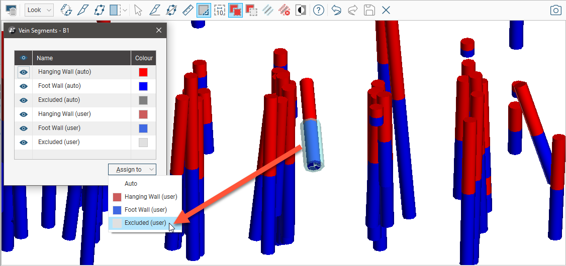
The categories shown for vein segments are:
- Hanging Wall (auto), Foot Wall (auto) and Excluded (auto). These are the categories Leapfrog Geo assigned segments to when the vein was created.
- Hanging Wall (user), Foot Wall (user) and Excluded (user). Segments assigned to these categories have been manually assigned to these categories. These are the categories you can assign selected segments to.
Assigning a segment to the Auto category sets it to the category Leapfrog Geo automatically assigned it to when the vein was created, which has the effect of undoing any edits made previously.
You can change the colours if you wish, but note that when the segments are displayed in the scene, the default colours make it easy to differentiate between automatically-categorised segments and those that have been edited.
The selected segments will be updated to reflect the change:
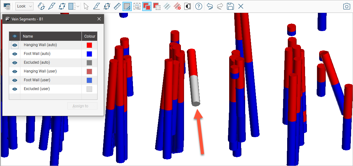
Click the Save button (![]() ) to view the effect of the changes.
) to view the effect of the changes.
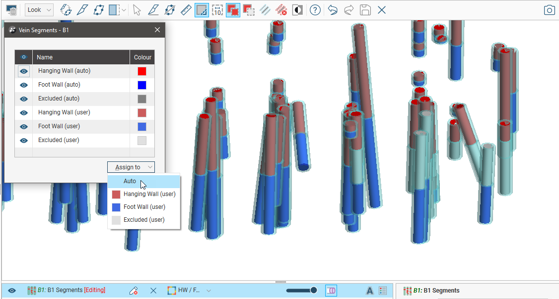
To revert to the categories assigned by Leapfrog Geo when the vein was created, select some segments and then assign them to the Auto category:
Editing Vein Midpoints
You can manually select vein midpoints and set them to excluded from processing. To do this, right-click on the vein midpoints object (![]() ) in the project tree and selecting Edit In Scene.
) in the project tree and selecting Edit In Scene.

If you manually edit midpoints, you can export the edits for use in other veins and models in the current project or in other projects. The edits are exported in a text file. See Exporting and Importing Pinchout, Segment and Midpoint Edits for more information.
If the vein midpoints object is already in the scene, you can edit it by clicking the Edit button (![]() ) in the shape list:
) in the shape list:

The Vein Segment Midpoints window will appear, along with a set of tools for selecting midpoints in the scene:

The process is similar to editing vein segments, as described in Editing Vein Segment Orientations above. The categories shown for midpoints are:
- Midpoint (auto) and Excluded (auto). These are the categories Leapfrog Geo assigned midpoints to when the vein was created. If Include mid points at the ends of holes is disabled, some midpoints may be automatically categorised as Excluded (auto), which is the case for three of the midpoints shown above.
- Midpoint (user) and Excluded (user). Midpoints assigned to these categories have been manually assigned to these categories. These are the categories you can assign selected points to.
Assigning a midpoint to the Auto category sets it to the category Leapfrog Geo automatically assigned it to when the vein was created, which has the effect of undoing any edits made previously.
Editing the Reference Surface
A vein includes a reference surface (![]() ) that represents the trend or form of the vein. When the vein is derived from drilling data, this is initially calculated as the best fit surface using the midpoints and the hangingwall and footwall surfaces. When derived from data other than drilling data, a planar reference surface is initially used. Whatever data source the vein is derived from, the reference surface setting can be changed to be a curved reference surface, a planar reference surface or another mesh in the project.
) that represents the trend or form of the vein. When the vein is derived from drilling data, this is initially calculated as the best fit surface using the midpoints and the hangingwall and footwall surfaces. When derived from data other than drilling data, a planar reference surface is initially used. Whatever data source the vein is derived from, the reference surface setting can be changed to be a curved reference surface, a planar reference surface or another mesh in the project.
Double-click on the reference surface in the project tree; this opens the Edit Vein Reference Surface window and you can see what option is being used for the surface. In this example, the B1 vein has been created from lithology data and so it has a curved reference surface and the midpoints for the vein lithology are used as Input values:

Each option is described below:
There is a great deal of flexibility in Leapfrog Geo for refining the reference surface, including the ability to created a surface in the Meshes folder from vein midpoints. A possible workflow is to:
1. Create an initial vein in the geological model.
2. Use the midpoints from this initial vein to create a mesh in the Meshes folder:
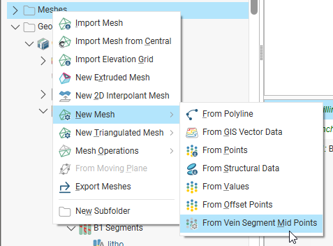
3. Refine the mesh using the Meshes folder tools.
See the Interpolated Meshes topic for information on creating and refining and interpolated meshes.
4. Use the mesh as a custom reference surface.
Curved Reference Surface
The Curved reference surface option is the default for veins created from lithology data and the objects used to build the reference surface are shown in the Input values part of the Edit Vein Reference Surface window:
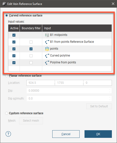
You can enable or disable the different data objects to see their effects on the vein by ticking and unticking the Active box, then clicking OK to reprocess the vein.
The Boundary filter setting for each object determines whether or not the data that lies outside the reference surface’s boundary is filtered.
- Tick Boundary filter so that the surface is only influenced by the data that falls inside the reference surface’s boundary.
- Untick Boundary filter if you want the surface to be influenced by the data both inside and outside the reference surface’s boundary.
Boundary filtering for the midpoints used to create a curved reference is controlled by the setting for the vein itself. See Boundary Filtering earlier in this topic for more information.
The Curved reference surface option is the default for veins created from lithology data, whereas the Planar reference surface option is the default for veins created from other types of data. In order for a vein created from data other than lithology data to use a curved reference surface, other data must be added to it. To add data, right-click on the reference surface in the project tree and select Add or Edit.
Using the Add option, you can add points data, GIS data or polylines to the surface. Using the Edit option, you can add a polyline to the reference surface, but its editing options are limited in that you can not add tangents or normals to the polyline.
Planar Reference Surface
Veins created from objects other than lithology data use a planar reference surface by default. To edit a planar reference surface, double-click on the reference surface in the project tree. This will open the Edit Vein Reference Surface window and display controls in the scene for adjusting the plane.
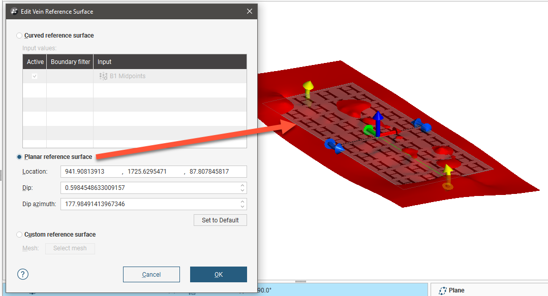
These handles work in the same manner as the moving plane controls, as described in The Moving Plane.
To use a planar reference surface for a vein created from lithology data, double-click on the reference surface to open the Edit Vein Reference Surface window, then select the Planar reference surface option. Adjust the plane in the scene, then click OK to reprocess the vein.
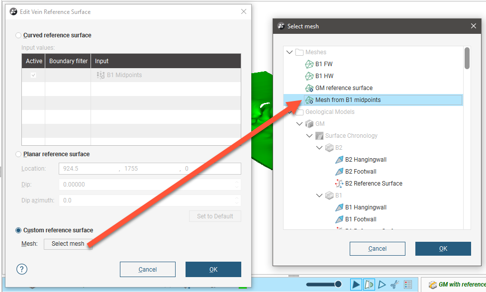
Custom Reference Surface
If you wish to use another surface in the project as a reference surface, double-click on the reference surface to open the Edit Vein Reference Surface window. Enable the Custom reference surface option, then select the mesh from those available in the project:
This option is useful if you wish to use an existing surface, such as the foot- or hanging-wall surface of an adjacent vein, as your vein’s custom reference surface, or if you need to use a fault surface to influence the trend of the vein. You can create and use your own custom vein surface, if needed.
Here, a thin folded layer has been modelled using a vein, created from a base lithology using sparse drilling data. The vein does not conform to known geology, crossing other modelled surfaces.
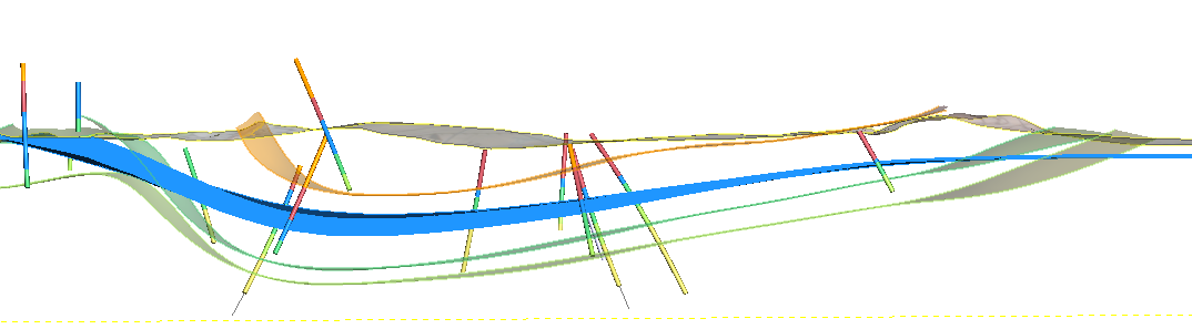
When the reference surface is edited to use a Custom reference surface with one of the existing surfaces in the model selected, the vein is modelled in a way that is more geologically reasonable:
Editing the Vein Boundary
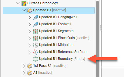
When a vein is first created, its boundary (![]() ) is empty:
) is empty:
Once a vein has been created, you can change its boundary by:
Editing the Boundary with a Polyline
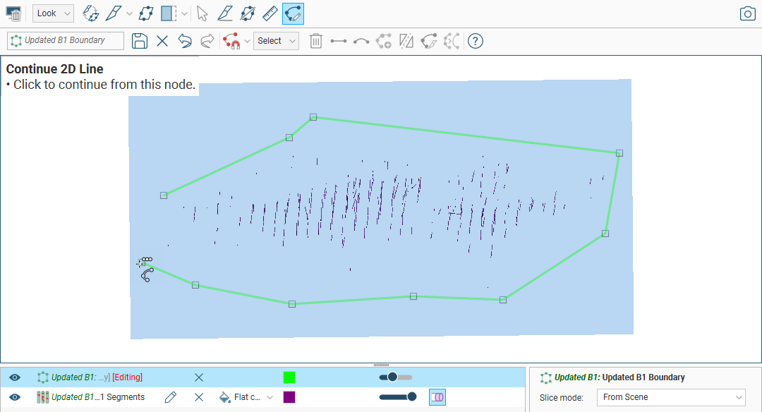
To edit the boundary using a polyline, right-click on it in the project tree and select Edit With Polyline. The current vein boundary will appear in the scene, together with drawing controls. Begin drawing the new boundary, as described in Drawing in the Scene, ensuring that the polyline drawn closes and does not intersect itself.
When you save the boundary, the vein will be updated to reflect the changes made. If you want to revert to the original boundary, right-click on the boundary object (![]() ) and select Delete Polyline.
) and select Delete Polyline.
If you have edited a vein’s boundary with a polyline and want to use the polyline for other veins’ boundaries, right-click on the polyline in the project tree and select Share. A copy will be saved to the Polylines folder which will be linked to from the vein. You can then use the polyline for other vein boundaries using the Add Polyline option. Edits made to the shared polyline in the Polylines folder will be updated wherever it is used.
Adding a Polyline to the Boundary
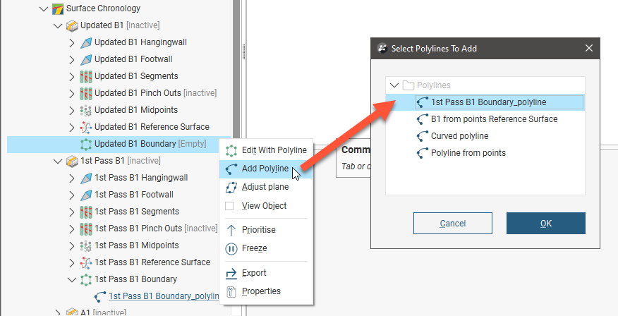
You can also add an existing polyline to the vein boundary. To do this, right-click on the vein’s boundary in the project tree and select Add Polyline. In the window that appears, select the polyline you wish to use:
If you have edited a vein’s boundary with a polyline, you can use that polyline for other vein boundaries. To do this, right-click on the vein that has been edited and share the polyline; a copy will be saved to the Polylines folder which will be linked to from the vein. You can then use the polyline for other vein boundaries using the Add Polyline option.
Adjusting the Boundary Plane
Another option for editing a vein boundary is to adjust the boundary plane. To do this, right-click on the boundary in the project tree and select Adjust Plane. The plane will be displayed in the scene, along with the Adjust Boundary Plane window. You can use the handles on the plane to adjust its position or you can enter the information in the Adjust Boundary Plane window.
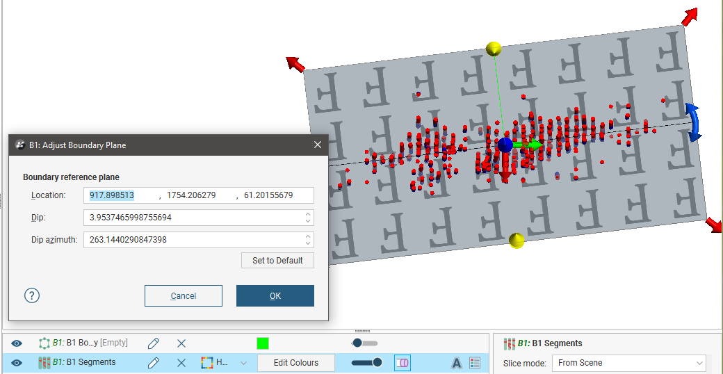
Click OK to apply the changes to the vein.
To revert to the original boundary plane, right-click on the boundary object and select Adjust Plane. In the Adjust Boundary Plane window, click on the Set to Default button and click OK.
Exporting and Importing Pinchout, Segment and Midpoint Edits
If you have made edits to vein pinchouts, segments, midpoints, you can export them for use in other veins and models in the current project or in other projects. The edits are exported in a text file.
To export vein edits, right-click on the vein in the project tree and select Export Vein Edits:
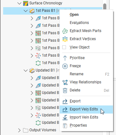
If the vein has no manual edits, a message will be displayed saying so. Otherwise, you will be prompted to save the file on your local hard drive.
Although the file containing the edits is a text file, editing it is not recommended.
To import vein edits, right-click on a vein and select Import Vein Edits. Select the file you wish to use, then click Open. The edits in the file will be applied to the vein. If there are edits in the file that don’t match the vein, a message will be displayed and a text file listing the errors will be saved on your local hard drive.
Got a question? Visit the Seequent forums or Seequent support
© 2023 Seequent, The Bentley Subsurface Company
Privacy | Terms of Use