
Using the Polyline Editor
In Leapfrog Geo, you can draw polylines to define or modify many surfaces, including lateral extents and contact surfaces. You can also use polylines to make adjustments to surfaces and create new GIS lines.
Polylines can be:
- Straight or curved 2D lines
- Straight or curved 3D lines
- Points with or without normals
To start creating a new polyline in thePolylines folder, right-click on the folder and select New Polyline. The polyline editor will be opened and you can begin drawing in the scene.
Polylines can also be created as part of editing surfaces; this works in the same manner as creating a polyline in the Polylines folder except that the polyline created is saved in the project tree as part of the object being edited.
Whether polylines have been created in Leapfrog Geo or imported into Leapfrog Geo, you can start editing an existing polyline in one of two ways:
- Right-click on the polyline in the project tree and select Edit Polyline. The polyline will be displayed in the scene and the polyline editor will be opened.
- If the polyline is already displayed in the scene, click on its Edit polyline button (
 ) in the shape list. The polyline editor will be opened.
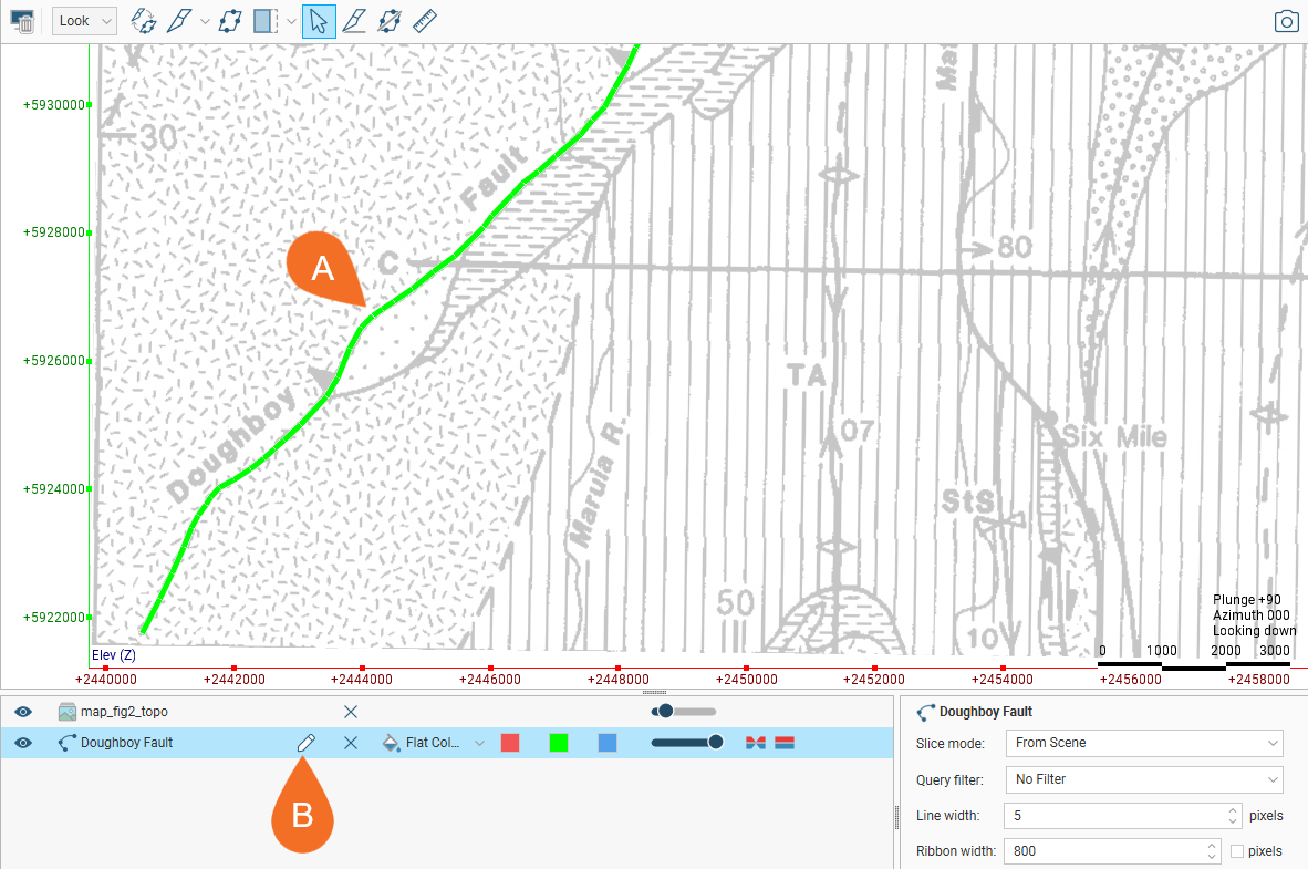
For example, here, we have a 2D polyline in the scene indicated by the solid green line (A). Click the button in the shape list (B) to start editing the polyline:
The polyline editor (C) is opened:
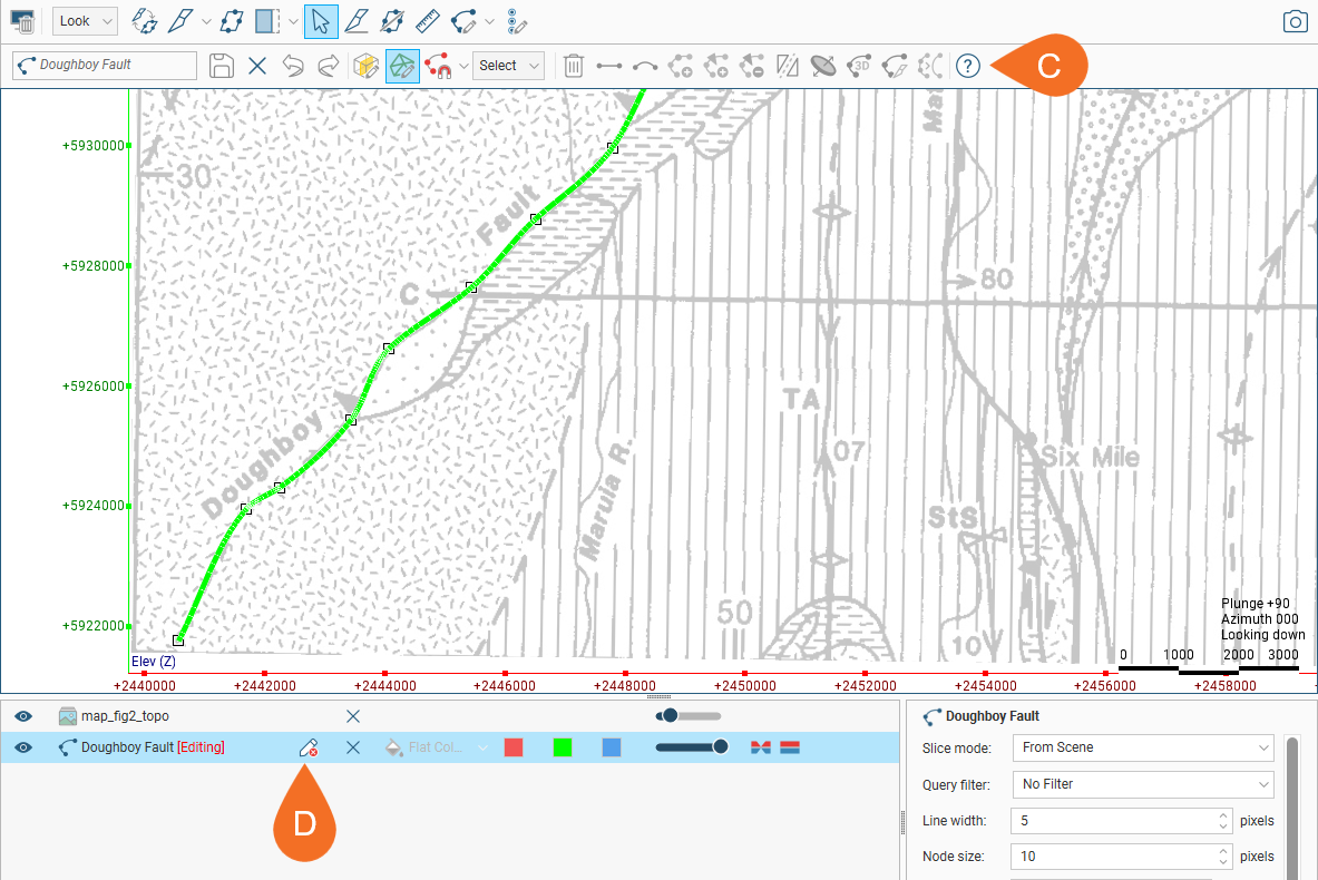
Clicking the edit button (D) again will close the polyline editor. If you have made changes to the polyline but have not yet saved them, you will be prompted to do so.
The rest of this topic describes the polyline editor and its settings. It is divided into:
- Drawing Modes and the Drawing Toolbar
- Drawing 3D Polylines
- Drawing 2D Polylines
- Node Snapping Options
- Editing Existing Polylines
- Polyline Properties
- Tangents and Ribbons
- Drawing Points
Drawing Modes and the Drawing Toolbar
When drawing in Leapfrog Geo, you can draw on surfaces or on the slicer.
- If you are drawing on surfaces (
 ), the line will be in 3D.
 - If you are drawing on the slicer (
 ), the line will be in 2D and locked to the plane it was drawn in. It can be converted to a 3D line.
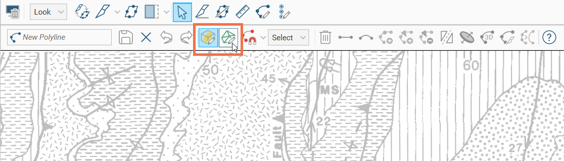
When you start drawing a polyline, the polyline editor will appear above the 3D scene. If you are drawing a GIS line or if the slicer was already in the scene, the drawing mode will be set to be on the slicer. Toggle between the two options using the toolbar buttons:
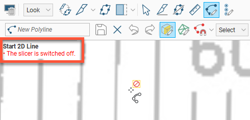
When drawing and otherwise working with the polyline, hints are displayed in the scene that show what actions are currently possible:
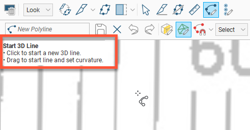
For example, if the mode is set to draw on the slicer (![]() ), you will be warned if the slicer is not in the scene:
), you will be warned if the slicer is not in the scene:
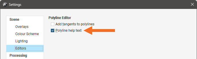
You can disable these hints once you are more familiar with how the polyline editor works. Open the Settings window by clicking on the Leapfrog Geo menu and selecting Settings. Click on Editors and disable the Polyline help text option:
The Draw Points(![]() ) tool is used to create new points.
) tool is used to create new points.
The Draw Lines tool has two modes:
- Draw Lines Without Tangents(
 ). In this mode, new polylines will be created without a tangent cone.
 - Draw Lines With Tangents(
 ). In this mode, new polylines will be created with a tangent cone.
To change between the Draw Lines Without Tangents and Draw Lines With Tangents modes, click the dropdown chevron next to the button and select the preferred option from the dropdown list.
You can change the initial setting of this control. To do this, click on the Leapfrog Geo menu and select Settings. Click on Editors and enable the Add tangents to polylines option.
For more about the use of polyline tangents, see Tangents and Ribbons later in this topic.
The tools in the second row are for controlling whether the polyline is drawn (on the slicer (![]() ) or on surfaces (
) or on surfaces (![]() )). The node snapping selector (
)). The node snapping selector (![]() ) allows you to specify the way a new node snaps to existing objects. The Select list lets you select different parts of the polyline.
) allows you to specify the way a new node snaps to existing objects. The Select list lets you select different parts of the polyline.
The other tools are for working with selected parts of the polyline:
- Making line segments straight (
 ) or curved ()
 - Adding nodes (
 ) to lines
 - Adding tangents to lines or reorienting selected tangents (
 )
) - Removing selected tangents (
 )
) - Flipping selected tangents and disks (
 )
) - Add disks to points (
 )
) - Converting a 2D polyline to 3D (
 )
) - Setting the slicer to a 2D polyline (
 )
) - Simplifying the line by reducing the number of nodes (
 )
)
There are also buttons for undoing (![]() ) and redoing actions (
) and redoing actions (![]() ), as well as saving the polyline (
), as well as saving the polyline (![]() ) or deleting selected parts of it (
) or deleting selected parts of it (![]() ).
).
Drawing 3D Polylines
To start drawing a 3D polyline:
- Be sure drawing on surfaces () is enabled, then
- Click the Draw lines() button.
You can then start clicking on objects in the scene to draw. Each time you click, a node will be added, with a straight polyline segment drawn between subsequent nodes. Right-click anywhere in the scene to discard the newly started segment and finish the line at the last node. As this is a 3D polyline, it will appear in the scene as a dashed line. Polylines are made up of these nodes and line segments.
To approximate a curve using straight polyline segments, create nodes that are close together.
You can also create curved polylines using bezier curves to get at least the approximate shape of a curve. Later on you can adjust the position of nodes and the bezier handles to refine the shape.
To create a curved polyline using bezier curves:
- Click where the line segment should begin.
- Move to where the curved line segment should end, then click-and-drag. This will place the new node, and a curved line between the last two nodes will appear.
- Drag the cursor while holding the mouse button down until the curved line lies where you want it, then release the mouse button.
At this point, another curved line segment will appear as you move the cursor. You can now take one of these three actions:
- Right-click to discard the newly started segment and finish the line at the last node.
- Move the cursor to where the next node will go, noting that as you move the cursor, the emerging curve may not be exactly where it is needed. Click-and-drag to place the next node. As you drag, you will be able to bend and shape the previous curved line segment to position the line where it should lie.
- Move the cursor until the new curved line segment lies where you want it, then click to place a node and start drawing a new straight line segment.
Creating a curved line using this technique usually takes some practise to get the shape you want. You will likely need to adjust the positions of the nodes and bezier handles to improve the curve.
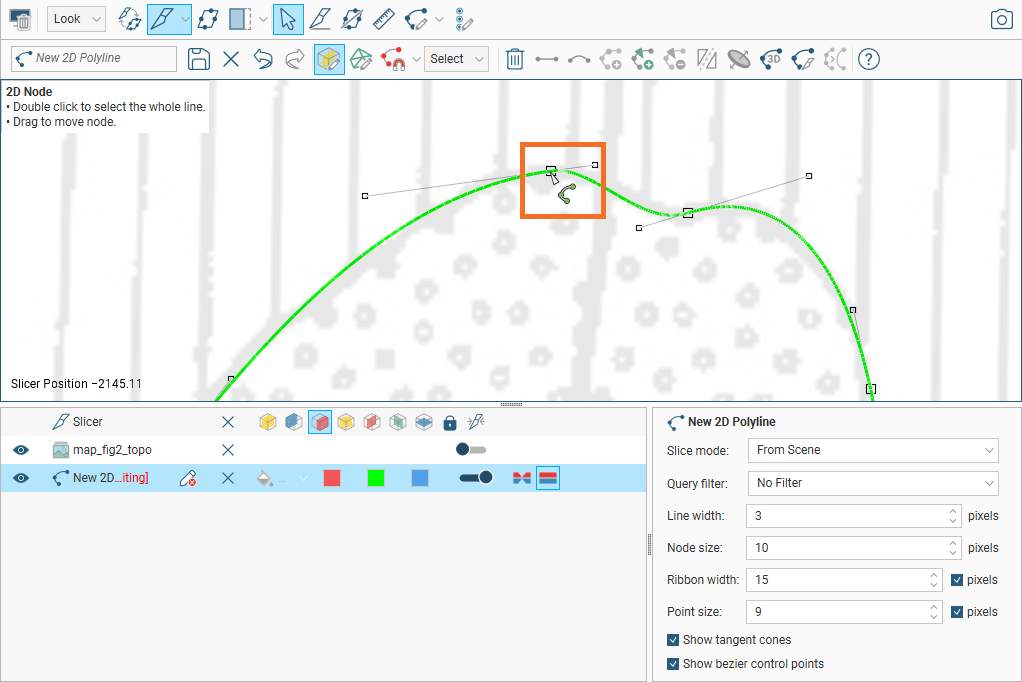
In the image below, the cursor is currently over a node.

Click to select a node and drag to move it in the scene parallel to the screen.
Repositioning the nodes may not be enough to get a curved polyline where you want it. You may also need to adjust the bezier control points to adjust how much the line segment curves.
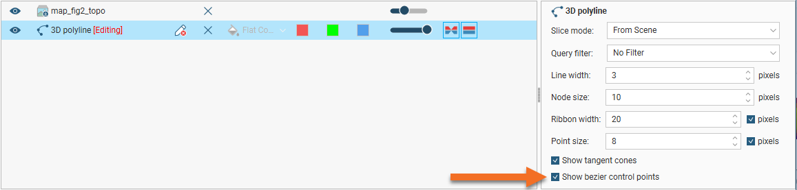
If you can’t see the bezier control points, click on the polyline in the shape list and enable the Show bezier control points option:
Repositioning a node in the scene will normally move it parallel with the screen, and this may detach the node from the object. You may instead prefer to snap the node to the surface in the scene. To do this, hold down the Ctrl key while moving the node.
Drawing 2D Polylines
2D polylines are drawn on a plane set by the slicer and are shown as an unbroken line, whereas a 3D polyline is shown as a dashed line.
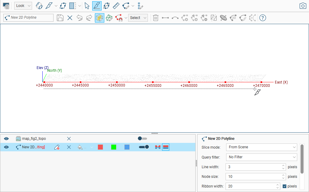
To begin, add an object to the scene. Here, a topography map is added. Next right-click on the Polylines folder and select New Polyline. The polyline editor will open:
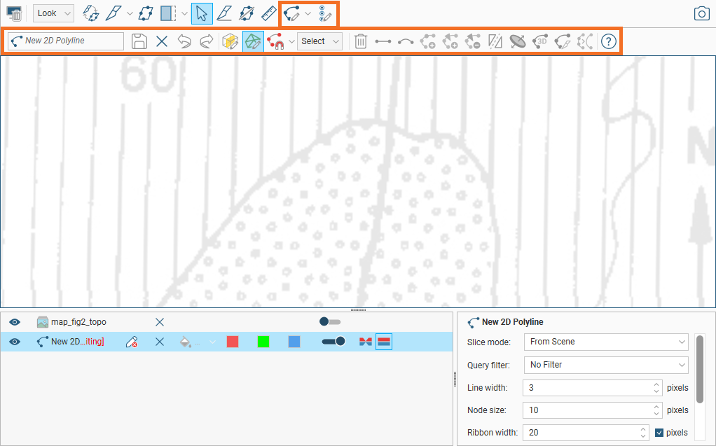
To start drawing a 2D polyline be sure drawing on the slicer (![]() ) is enabled, then use the slicer to create a slice. You may need to reorient the object in the scene as in the case here:
) is enabled, then use the slicer to create a slice. You may need to reorient the object in the scene as in the case here:
Click the Draw lines(![]() ) button.
) button.
Then, drawing a 2D polyline is similar to drawing 3D polylines, except that drawing is restricted to the 2D plane set by the slicer.
To convert a 2D polyline into a 3D polyline, double-click on the line to select the whole line, then click the 3D polyline button (![]() ).
).
Node Snapping Options
With the node snapping selector (![]() ), you can choose how a new node snaps to existing objects. You have the following options:
), you can choose how a new node snaps to existing objects. You have the following options:
- Snap to polyline nodes (for 2D and 3D polylines)
- Snap to mesh edges (for 3D polylines only)
- Snap to mesh vertices (for 3D polylines only)
It is not possible to snap to a mesh edge or vertex when drawing 2D polylines as it is almost impossible to locate such a position on the slicer.
With a node snapping mode selected, the new node will snap to the object when you click to locate the node. To see the effect of snapping, zoom in close.
As you get close to an object the new node is able to snap to, it will pull the new node to the object like a magnet. When Snap to mesh edges or Snap to mesh vertices options are selected for 3D lines, if an object is not close enough, the cursor and the hint text will indicate that no object is under the mouse cursor. As you approach an edge or a vertex, the cursor will pull to that edge or vertex to make clicking on the snap-to object easy.
Editing Existing Polylines
Add the polyline to the scene, then select the polyline in the shape list and click its Edit polyline button (![]() ). Click the Select tool (
). Click the Select tool (![]() ) to make changes to the polyline.
) to make changes to the polyline.
- Click on a node to move it.
- Click on a segment away from a node and drag it to change its curvature.
- Click on one or more segments, then make them straight (
 ) or curved (
 ).
). - Select a point on the polyline, then click () to add a node.
- Select a point on the polyline. The point selected is indicated in the scene by a red cone. You can then click () to add a tangent oriented in the direction of the camera.
- Select a tangent and click () to change the orientation of the segment to that of the camera.
- Select a tangent and click () to remove the tangent cone.
- Select a tangent and click () to flip it.
Begin drawing again by selecting the Draw lines button (![]() ). To continue from an existing node at the start or end of a polyline, click on the node.
). To continue from an existing node at the start or end of a polyline, click on the node.
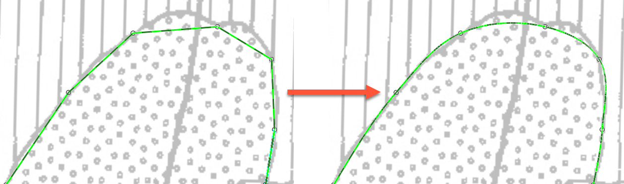
Use as many nodes as necessary to draw the polyline. You can later reduce the number of nodes using the Simplify polyline tool (![]() ). Each time this tool is used, Leapfrog Geo attempts to halve the number of nodes on the select segments:
). Each time this tool is used, Leapfrog Geo attempts to halve the number of nodes on the select segments:

Although you can make the line curved while adding nodes, an easy way to draw a curved polyline is to simply click to add a series of points. Set the curvature of the whole line by selecting all segments and then clicking the Make selected segments curved button (![]() ):
):
You can then make any adjustments to the curves required by dragging the segments or using the bezier control points.
Polyline Properties
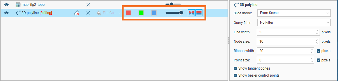
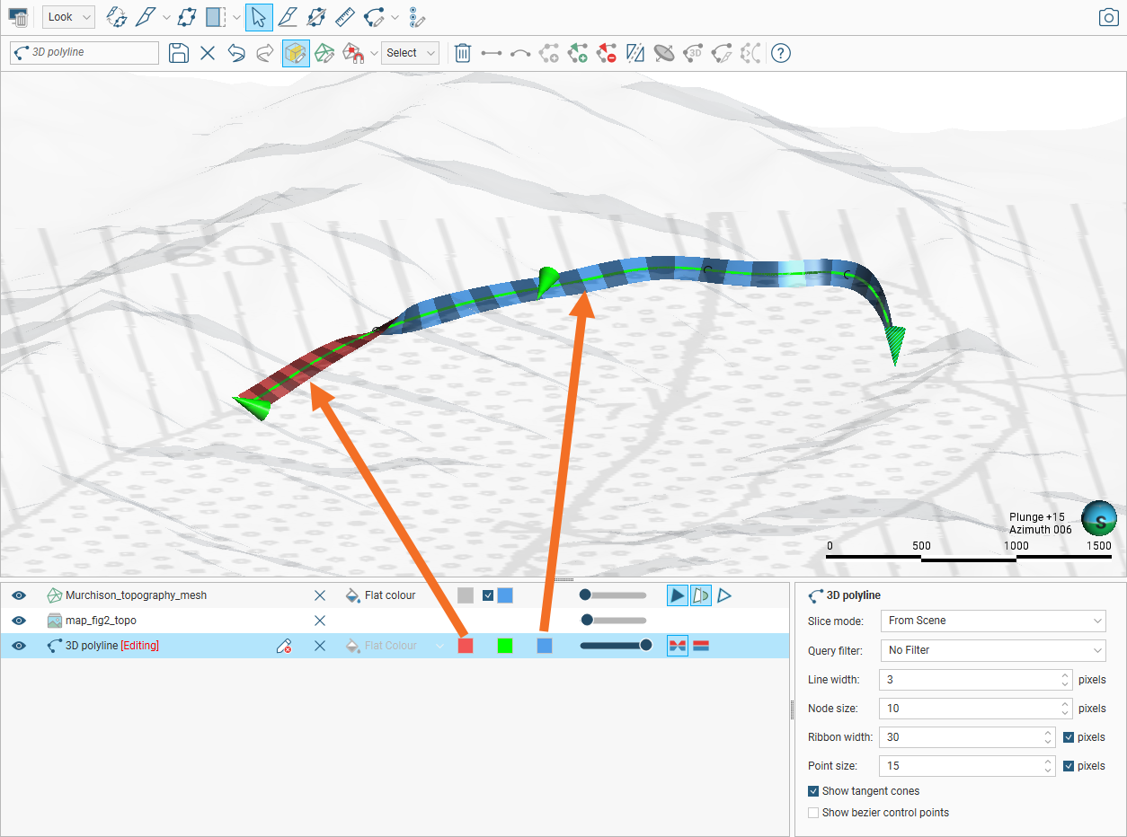
In the shape list, you can control the colour of the positive (red) and negative (blue) surfaces of the line and of the line itself (green):
For contact surfaces, the colour of the positive and negative sides of a ribbon will be determined by the lithologies or categories assigned to either side of the surface.
With the controls in the properties panel, you can change the size of different parts of the polyline to make working with the polyline easier.
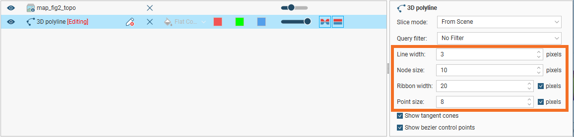
For Ribbon width and Point size, the setting is, by default, in pixels, but both can be displayed in real-world size by unticking the pixels box, which may make editing the polyline easier in some circumstances.
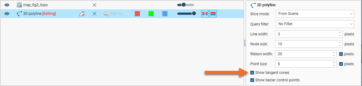
You can also choose whether or not to show tangent cones and bezier control points.
Tangents and Ribbons
Adding a tangent to a polyline gives the polyline a twist orientation.
When polylines are drawn, whether or not there is a tangent cone associated with the polyline depends on the mode of the Draw Lines toolbar button.
You can add tangent cones to specify an orientation or twist to the polyline by clicking at a point along the polyline and then clicking the Tangent button (![]() ). A tangent cone is added to the polyline in the scene. When a new tangent is added, the tangent’s orientation is taken from the camera angle.
). A tangent cone is added to the polyline in the scene. When a new tangent is added, the tangent’s orientation is taken from the camera angle.
To reorient a tangent, click on it in the scene, change the camera angle to reflect the orientation you wish to set, then click the Tangent button (![]() ).
).
You can also flip selected tangents by clicking on the Flip tangents and disks button (![]() ).
).
You can add as many tangents as required, although it is best to keep them to a minimum.
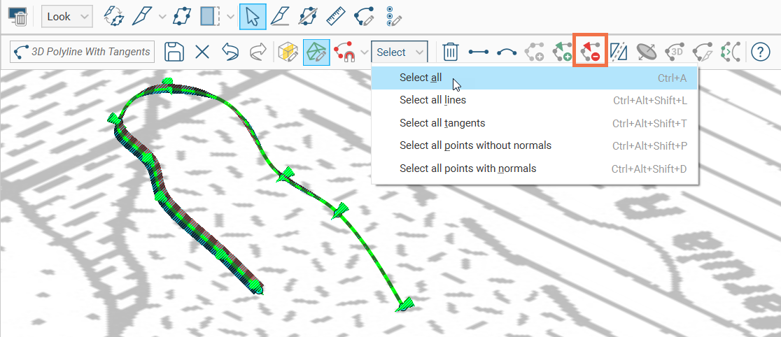
If you want to remove a tangent, select the tangent and click on the Remove all selected tangents button (![]() ). To quickly remove all tangents, you can do any one of the following:
). To quickly remove all tangents, you can do any one of the following:
- Choose Select all tangents from the toolbar then click on the Delete selected items button (
 )
) - Ctrl + Shift + Alt + T then hit the Delete key
- Choose Select all then click on the Remove all selected tangents button ()
- Ctrl + A then R
You can hide the tangent cones in the scene, if it makes drawing difficult. To do this, click on the polyline in the shape list and disable the Show tangent cones option:
When a polyline has a tangent, it can be visualised in the scene as a ribbon. The Surface ribbon(![]() ) and Normal ribbon(
) and Normal ribbon(![]() ) options help you to determine the orientation of the polyline in the scene. The surface ribbon reflects the orientation of the polyline and the normal ribbon is perpendicular to the surface ribbon.
) options help you to determine the orientation of the polyline in the scene. The surface ribbon reflects the orientation of the polyline and the normal ribbon is perpendicular to the surface ribbon.
For example, click on the Surface ribbon button (![]() ) to determine which side of the polyline is positive (red) and which side is negative (blue):
) to determine which side of the polyline is positive (red) and which side is negative (blue):
If you are having trouble seeing the ribbons, you can change their size using the Ribbon width control in the properties panel.
Drawing Points
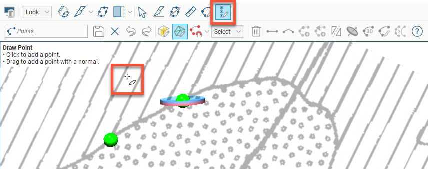
Polylines can include points, which are drawn using the Draw points tool (![]() ). Clicking adds a point, and clicking and dragging adds a point with a normal. Normals are shown in the scene as disks intersecting the points. The scene below shows one point with a normal and one without:
). Clicking adds a point, and clicking and dragging adds a point with a normal. Normals are shown in the scene as disks intersecting the points. The scene below shows one point with a normal and one without:
To move a point without a normal, switch to the Select tool (![]() ). Click on the point and drag it. To add a normal to the point, click on it in the scene and click the Add disk button (
). Click on the point and drag it. To add a normal to the point, click on it in the scene and click the Add disk button (![]() ).
).
To edit the orientation of a point with a normal, click on it in the scene. There are two rotation modes, and a click on the disk will change between modes.
- In one rotation mode, yellow and blue arrows show how dragging the disk will change the dip and azimuth of the disk. The yellow arrows indicate the direction of rotation when you click-and-drag the disk. Change the position of the pointer on the disk to switch the rotation selection to the other pair of arrows.
- In the other rotation mode, an extended translucent disk extends out from the point at right-angles to the point’s disk. Around the edge of the disk are four blue arrows indicating the rotational direction. Click-and-drag the point’s disk to adjust the disk angle. Change the position of the pointer on the disk to change the angle of the rotation plane on the point’s disk.
You can also change the orientation of a disk by drawing over it. To do this, make sure the Draw points tool (![]() ) is selected. Hold the cursor over the point you want to edit. The cursor will turn green to indicate that you can adjust the disk’s angle. Drag to adjust the angle and release the mouse button when finished.
) is selected. Hold the cursor over the point you want to edit. The cursor will turn green to indicate that you can adjust the disk’s angle. Drag to adjust the angle and release the mouse button when finished.
You can also flip selected disks by clicking on the Flip tangents and disks button (![]() ).
).