Enabling and Editing Vein Pinch Outs
When veins are created from drilling data, vein walls can be set to pinch out where drilling data does not include the designated vein lithology. Pinch outs are achieved by creating ‘outside’ intervals on drillholes that do not have an interior vein segment. These intervals are then flipped with respect to interior vein intervals, which, in effect means the footwall and hangingwall orientation has the opposite sense to the nearest interior intervals. This forces the hangingwall and footwall surfaces to cross, thereby pinching out.
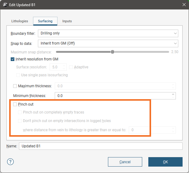
The Pinch out option is disabled when a vein is first created. To enable it, double-click on the vein in the project tree and click on the Surfacing tab. Tick the box for Pinch out:
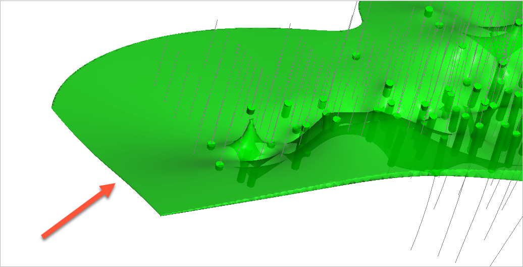
For this vein, the green cylinders indicate vein lithology intervals. The surface continues to the boundary even where there are no drillholes that have vein lithology intervals:
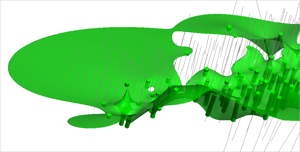
When the vein is set to pinch out, it tapers out where there is no vein lithology data:
There are two further settings that relate to whether or not a drillhole trace has data logged:
- The Pinch out on completely empty traces setting relates to whether or not pinch outs are created for drillholes where no lithology data has been logged, neither vein nor background lithology.
- The Don’t pinch out on empty intersections in logged holes setting relates to whether or not pinch outs are created for drillholes that have data logged that intersects the vein’s hangingwall and/or footwall surfaces.
There is also the option to manually exclude some pinch out segments. Each of these is discussed in detail below:
- Pinch Out on Completely Empty Traces
- Don’t Pinch Out on Empty Intersections in Logged Holes
- Manually Excluding Pinch Out Segments
Pinch Out on Completely Empty Traces
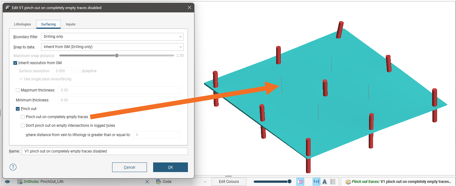
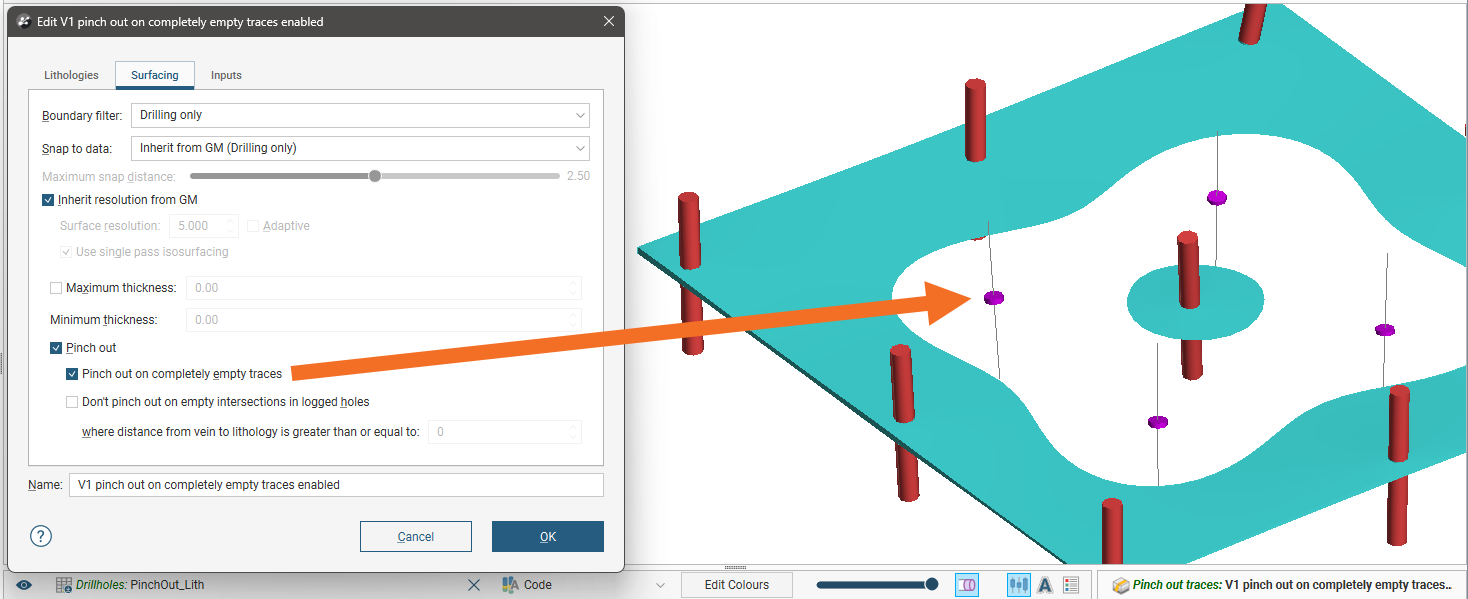
The Pinch out on completely empty traces setting relates to whether or not pinch outs are created for drillholes where no lithology data has been logged, neither vein nor background lithology. Enabling the setting results in pinch outs being created where such traces intersect the vein footwall and/or hangingwall surfaces, resulting in a final vein that is empty around those pinch outs.
To illustrate the effect of this setting, we have an artificial dataset that has four traces with no logged data. When Pinch out on completely empty traces is disabled, the vein does not pinch out where it there are no actual vein segments:
When the option is enabled, however, pinch outs (pink) are created around the empty traces and the vein pinches out around them:
Don’t Pinch Out on Empty Intersections in Logged Holes
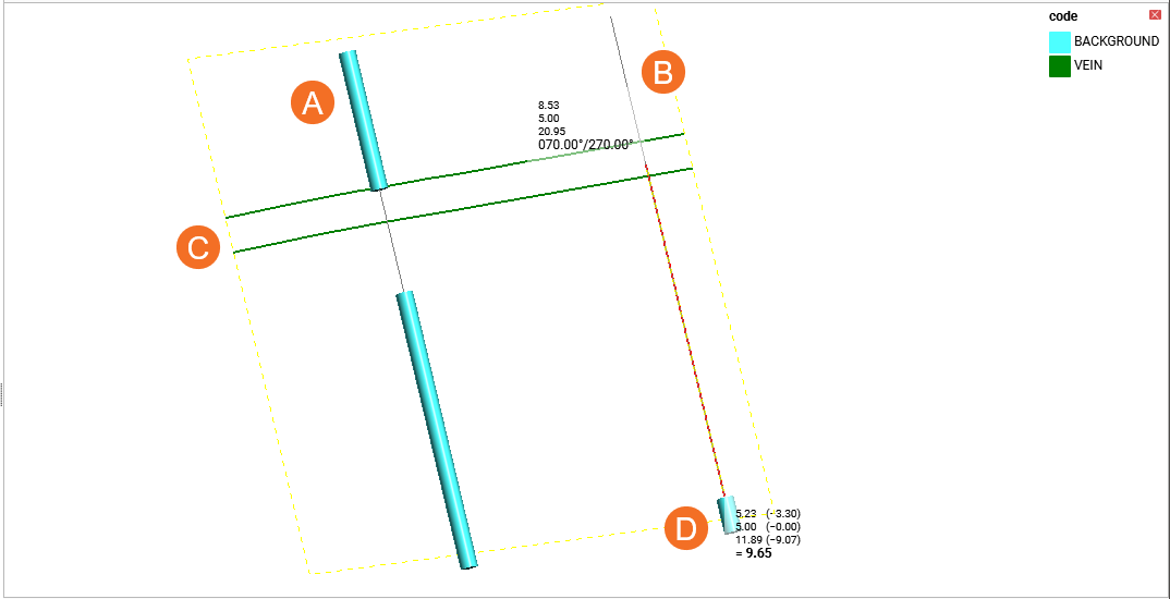
The Don’t pinch out on empty intersections in logged holes setting relates to whether or not pinch outs are created for drillholes that have data logged that intersects the vein’s hangingwall and/or footwall surfaces. Whether or not the logged lithology ‘intersects’ the hangingwall and/or footwall surfaces is determined by a distance parameter; if there is logged data but it fall outside the distance specified, the intersection is regarded as ‘empty’ and no pinch out will be created.
Again, we have an artificial dataset to illustrate the effect of this setting. Here there are two drillholes (A and B) that do not contain the vein lithology; they do, however, contain other lithologies and so are regarded as logged. The scene is sliced and so the lines (C) show where the vein’s hangingwall and footwall surfaces intersect each drillhole. We can see that A has a logged interval that directly contacts the hangingwall surface, whereas the logged interval (D) in drillhole B is quite distant from the footwall surface:
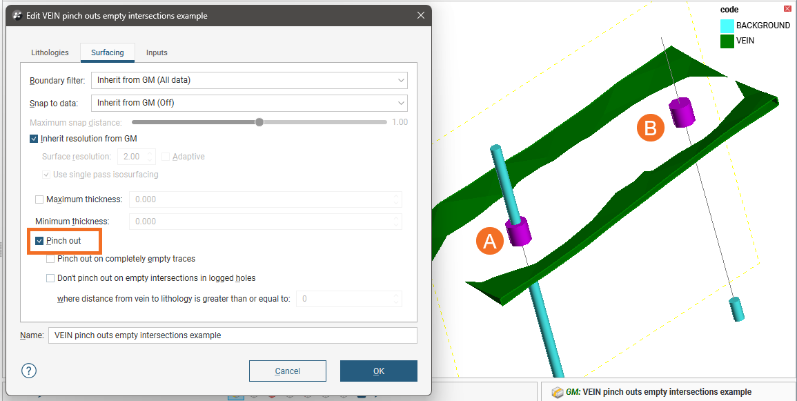
Enabling only the Pinch out setting creates pinch outs where both drillholes intersect the vein, which is as expected:
Enabling Don’t pinch out on empty intersections in logged holes results in the vein pinching out where it intersects drillhole A, but it does not pinch out for drillhole B:
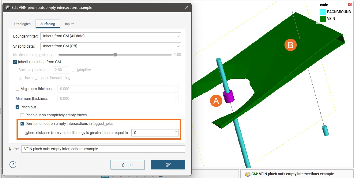
This is because the interval in drillhole B is outside the distance specified and so the intersection between the vein and drillhole B is regarded as empty.
Increasing the distance value results in the vein also pinching out where it intersects drillhole B:
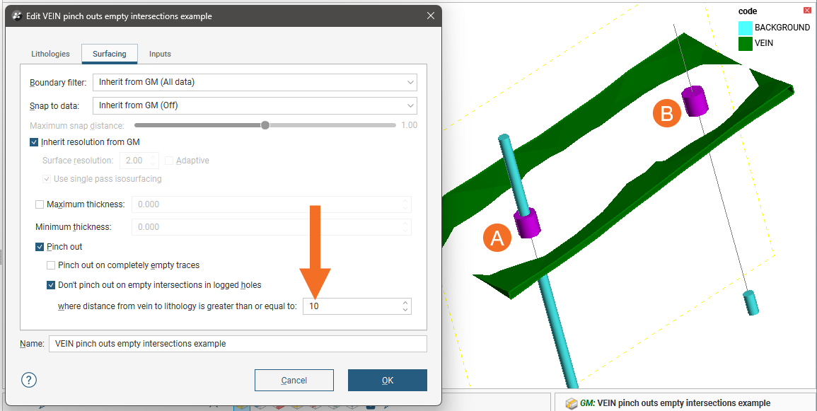
The distance value can be used to indicate how far away logged data can be while still informing the vein surface. If, however, it does not seem geologically reasonable to adjust vein pinch out behaviour in this way, an alternative is to manually exclude some pinch out segments.
Manually Excluding Pinch Out Segments
You can change how much a vein pinches out by manually excluding some pinch out segments. To do this, right-click on the pinch out segments ( ) in the project tree and select Edit in Scene:
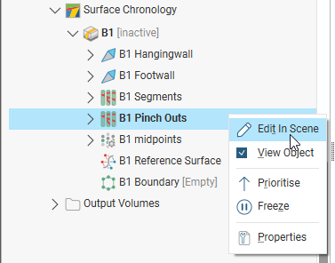
If you manually edit pinch outs, you can export the edits for use in other veins and models in the current project or in other projects. The edits are exported in a text file. See the Exporting and Importing Vein Edits topic for more information.
You can also add the pinch out segments to the scene and click the Edit button ( ) in the shape list:
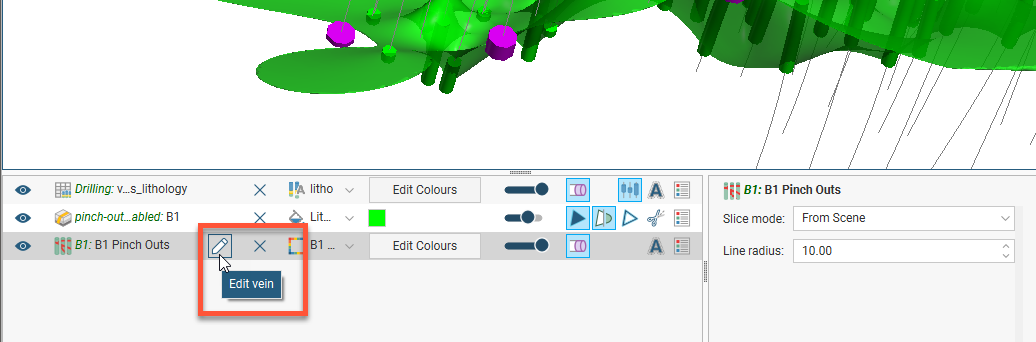
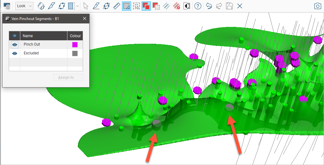
The Vein Pinchout Segments will appear, along with a set of tools for selecting segments in the scene:
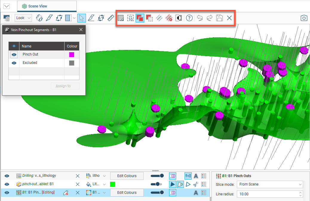
To select segments, click on the Select segments button ( ) and click the Add segments button (
 ). In the scene, draw a line across each segment you wish to select:
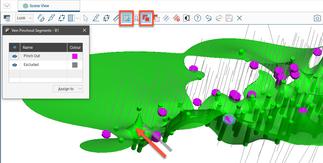
Note that the segments displayed in the scene below are the pinch out segments rather than the drillhole segments shown in earlier scenes. The grey segments are excluded and the currently selected segment is highlighted in the scene.
Selected segments are highlighted in the scene. If you accidentally select the wrong segment, either:
- Click the Remove segments tool (
 ) and draw across the point once again.
- Hold the Ctrl key while drawing across the point.
You can also:
- Select all visible segments by clicking on the Select all tool (
 ) or by pressing Ctrl+A.
- Clear all selected segments by clicking on the Clear selection tool (
 ) or by pressing Ctrl+Shift+A.
- Swap the selected segments for the unselected segments by clicking on the Invert selection tool (
 ) or by pressing Ctrl+I.
To change the width of the line used to select segments, click on the Change line width button ( ) and enter a new value. You can keep the Set Line Width window open while you select intervals so you can change the line width as required:
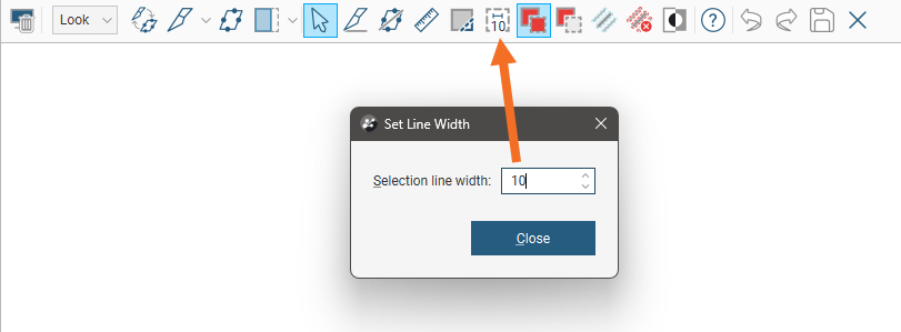
Note that the current line width is indicated by the Change line width button.
When you have selected at least one segment, click on the Assign to button, then select the category you want to assign the selected segments to:
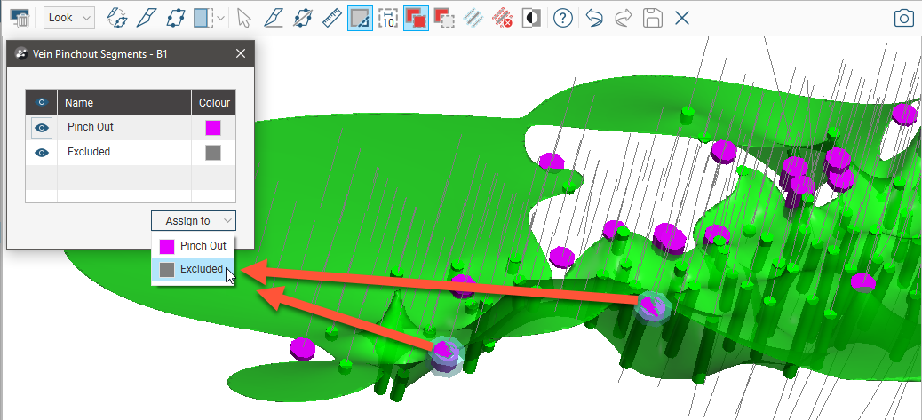
The selected segments will be updated to reflect the change:
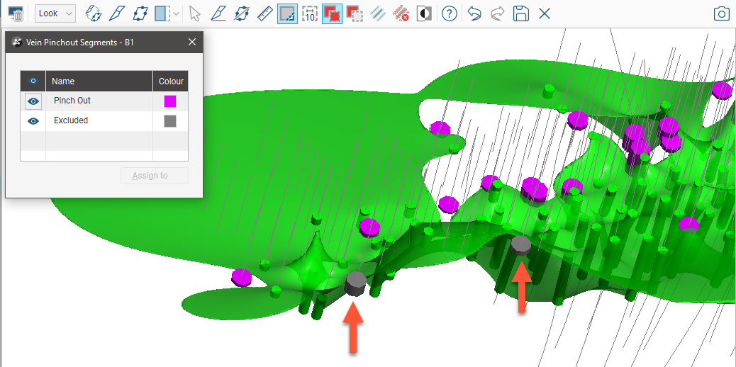
Click the Save button ( ) to view the effect of the excluded pinch out segments on the vein. In this example, excluding the two segments results in the vein terminating at the boundary of the geological model: