The Project Tree
This topic provides an introduction to working with the project tree. It is divided into:
- Project Tree Keyboard Shortcuts
- Restricted Objects
- Subfolders
- Finding Objects
- Deleting Objects
- Renaming Objects
- Copying Objects
- Comments
- Sharing Objects
- Unsharing a Polyline
The series of folders in the project tree are used to organise objects such as maps, images and data sets into categories. These folders also provide tools that let you import information into the project and generate models. Right-click on each folder to view the actions you can perform using that folder.
You can also right-click on objects within the top-level folders to view more information on that object or carry out actions specific to that object. For example, right-clicking on a table of imported drillhole data reveals a menu showing possible actions:
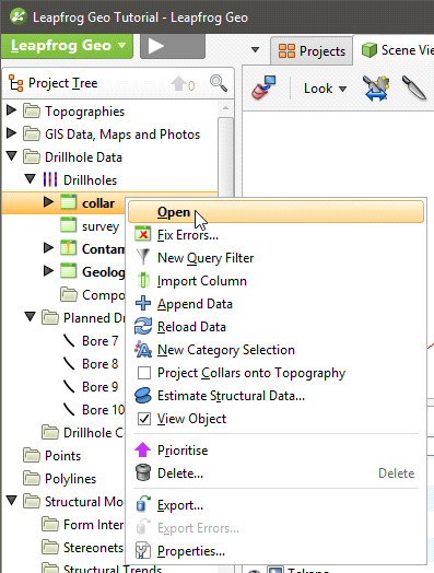
When a bold option appears in the right-click menu, as Open does in the menu above, that option can also be selected by double-clicking on the object.
You can select more than one object in the project tree by holding down the Shift key or the Ctrl key while clicking. This is useful for viewing or deleting multiple objects at once.
The way folders and objects are organised in the project tree lets you reveal or hide information about an object to focus on objects you are currently working with. This is also useful when you are exploring a project and want to determine how something was put together. The arrows next to objects in the project tree let you reveal or hide an object’s details to focus on objects you are currently working with.
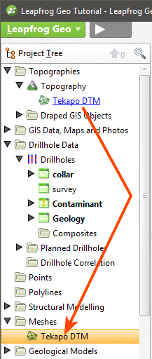
The mesh itself is stored in the Meshes folder, but is hyperlinked to from wherever it is used in the project.
The Drillhole Data folder and the Drillholes object have been expanded to show the drillhole data tables. Tables shown in bold are those displayed in the scene.
Folders that have no arrow have no detail stored.
Expanding a geological model reveals information about how it was built. Here, a geological model has been expanded to show the basic objects that make up a model:
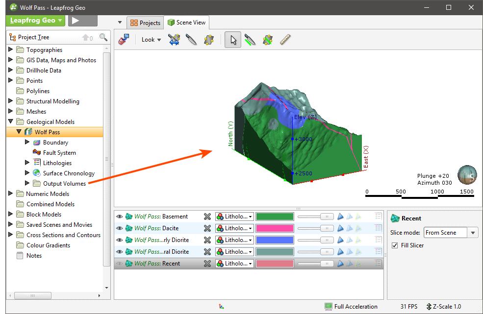
The five objects underneath the geological model “GM” represent the five basic parts of a geological model:
- The Boundary object defines the outer limits of the geological model.
- The Fault System object defines faults and their interactions in the geological model.
- The Lithologies object defines the lithologies in the model.
- The Surface Chronology object defines the structure of the model’s contact surfaces.
- The Output Volumes folder contains the generated units (outputs) that make up the geological model.
Here, boundary objects for a geological model have been expanded to show how they were created:
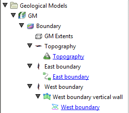
The Topography object is included as the model’s upper boundary. The “East boundary” object was created using a polyline from the Polylines folder and the “West boundary” object was created using a GIS data object in the GIS Data, Maps and Photos folder. Clicking on the hyperlinks will locate the object from which the extent was created.
Project Tree Keyboard Shortcuts
Keyboard shortcuts for navigating in the project tree are as follows:
| Key(s) | Action |
|---|---|
| Up and down arrows | Navigate up and down the tree |
| Right arrow | Expand folder/object or go down one level |
| Left arrow | Close folder/object or go up one level |
| Ctrl+shift+left arrow | Close all folders/objects |
| Shift+right arrow | Expand the selected folder/object and any objects in it |
| Shift+left arrow | Close the selected folder/object and any objects in it |
| Ctrl+A and Ctrl+/ | Selects all folders and objects |
| Ctrl+F | Search for objects |
| Enter | The equivalent of double-clicking on an object |
| Ctrl-X | Cut an object or subfolder. Use with Ctrl-V to move objects and subfolders. |
| Ctrl-V | Paste an object or subfolder |
To view a PDF of all Leapfrog Geo keyboard shortcuts, click here.
Some actions are not available until data has been imported into the project.
Restricted Objects
Some objects may appear in the project tree as restricted:
Restricted objects were created using features only available in modules. You can display restricted objects in the scene and change how they are displayed, but you cannot make changes to the objects themselves. Contact Customer Support as described in Getting Support for more information about licensing modules.
Subfolders
In many top-level project tree folders, you can create subfolders that help in organising large numbers of data objects. For example, here colour gradients have been organised into subfolders:
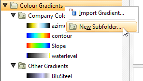
To add a subfolder, right-click on a folder in the project tree and select New Subfolder. Add objects to subfolders by dragging and dropping them. You can also use Cut (Ctrl-X) and Paste (Ctrl-V) shortcuts to move objects and subfolders.
Subfolders can be renamed, moved and deleted, but cannot be moved to other top-level folders.
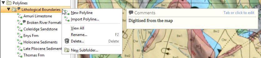
Subfolders have the same right-click commands as their parent folder, which means you can import or create new data objects inside the subfolder rather than in the parent folder. You can also add comments to folders to aid in keeping data organised:
You can view all objects in the subfolder by dragging the folder into the scene or by right-clicking on the subfolder and selecting View All.
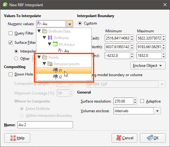
When lists of objects are displayed, the subfolder organisation will be reflected in the list. For example, when creating an interpolant, the list of data objects that can be interpolated is displayed organised by subfolder:
Subfolders cannot be created in the Drillhole Data folder, although they can be created in the Composites and Planned Drillholes folders.
Finding Objects
To find objects in the project tree, click the search button at the top of the project tree:
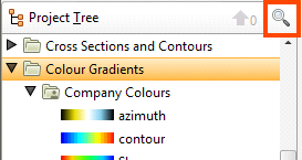
You can also click anywhere in the project tree and type “Ctrl-F”.
The Find window will be displayed:
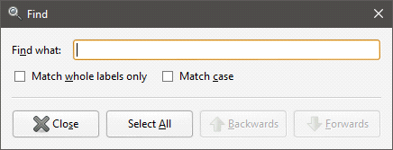
Enter the information you are searching for, then click Backwards or Forwards to locate the object in the project tree.
Deleting Objects
When you delete an object from the project tree, a window will be displayed listing all other objects in the project that will also be deleted and those that will be reprocessed. Some objects will be put into an error state; you will need to correct those errors before the affected object can be used elsewhere in the project.
Consider carefully the effects on other objects in the project, as once an object is deleted, it cannot be recovered.
Deleting data from the project may cause other objects to be reprocessed, which can take some time.
To delete more than one object from the tree, hold down the Shift key or the Ctrl key while selecting objects.
Renaming Objects
When an object is created in Leapfrog Geo, it is given a default name. It is a good idea to give objects in Leapfrog Geo names that will help you distinguish them from other objects, as large projects with complicated models will contain many objects.
To rename an object in the project tree right-click on the object and select Rename. The Rename Object window will be displayed:
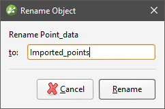
Enter a new name for the object. Click Rename to change the object’s name.
Copying Objects
Many objects in the project tree can be copied. Right-click on an object and select Copy. You will be prompted to enter a name for the object’s copy.
The copied object is not linked to the original object. However, if the original object is linked to other objects in the project, the copy will also be linked to those objects.
Comments
Another aid to documenting work in a project is comments.
You can record comments on many objects in the project tree, including subfolders. This can be helpful when the project contains many objects and when several different people are working on a model. Objects that have comments are indicated in the project tree by a comment balloon (![]() ). The comment will be displayed when you right-click on the object:
). The comment will be displayed when you right-click on the object:
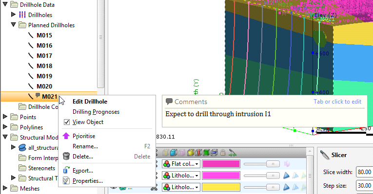
Tab or click to add a new comment or edit an existing one. You can also add standard information to a comment, such as date and time.
You can add information about the project as a whole using the Notes object (![]() ), which is the last object in the project tree. Double-click on the Notes object to open it and add information.
), which is the last object in the project tree. Double-click on the Notes object to open it and add information.
Sharing Objects
Some objects are created as part of working with other objects and are not available elsewhere in the project. An example of this is a polyline drawn as part of creating a geological model boundary. To share such objects within the project, right-click on the object in the project tree and click Share. The shared object will be copied to the relevant location in the project tree and a hyperlink added to the object it was shared from.
For example, here a polyline created as part of a lateral extent is shared:
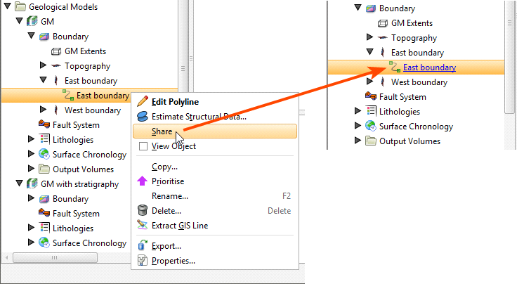
The polyline is saved to the Polylines folder and a hyperlink to it appears as part of the geological model’s boundary. Whenever the polyline is updated, changes will be made wherever it is shared in the project.
Unsharing a Polyline
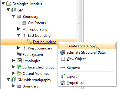
Polylines that have been shared can be unshared by making a local copy of the polyline. To do this, right-click on the shared polyline and select Create Local Copy:
The polyline in the Polylines folder remains, but a local copy of it is made and the hyperlink to the Polylines folder copy is deleted. This means you can now work on, for example, the Polylines folder copy without changes to it affecting the geological model’s copy.