Modifying Surfaces
This topic describes aspects of modifying surfaces in Leapfrog Geo. It is divided into:
- Surface Resolution in Leapfrog Geo
- Adding Data to Surfaces
- Honouring Surface Contacts
- Global Trends
- Structural Trends
- Editing Surfaces with Polylines
- Editing Surfaces with Structural Data
Surface Resolution in Leapfrog Geo
In Leapfrog Geo, meshes are used to represent surfaces in the form of vertices and triangles that define the 3D shape of the surface. The resolution of a surface is controlled by the size of the triangles used to create a surface. A lower surface resolution value means smaller triangles and, therefore, a finer resolution. A higher surface resolution value will take less time to process but the surface may not show the level of detail required.
When a surface is imported, Leapfrog Geo automatically sets a surface resolution based on the information in the file. It is not possible to change the resolution of surfaces imported into Leapfrog Geo.
When surfaces are created, Leapfrog Geo sets a default resolution based on the data available. You can set a lower value, but calculations will take longer. In addition, the resolution for many surfaces can be adaptive; that is, areas closer to data will have a finer resolution than areas further away from data.
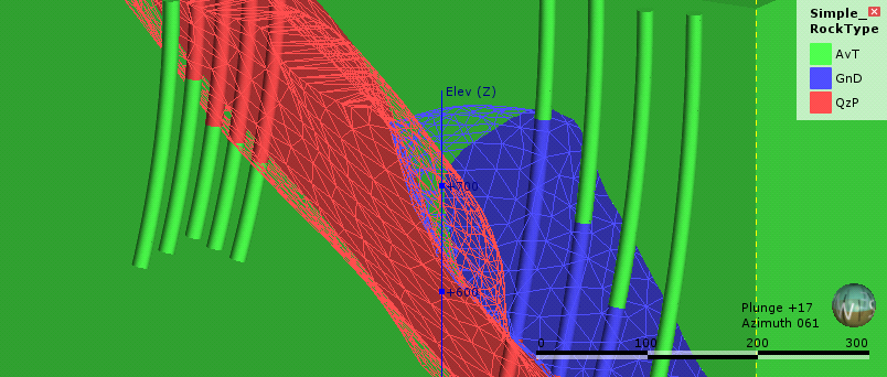
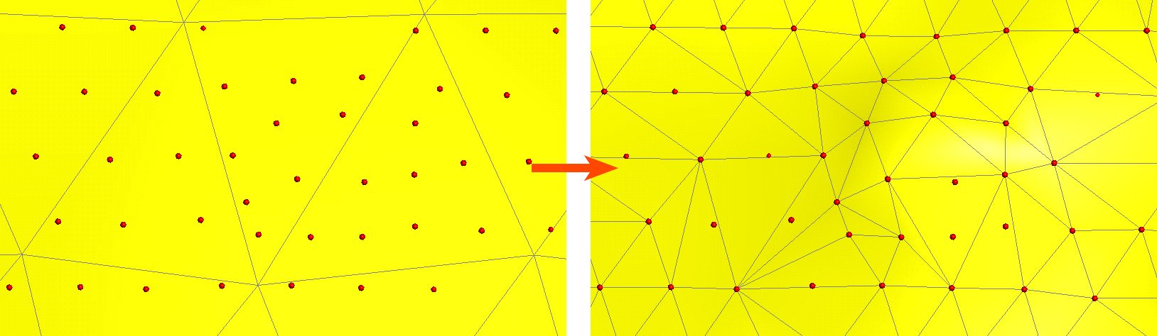
To see the effect of different resolution settings, consider a simple geological model of three rock types. Here, the surface resolution is set to 50 and the adaptive isosurfacer is disabled:
Here, the resolution has been reduced, which results in smaller triangles:
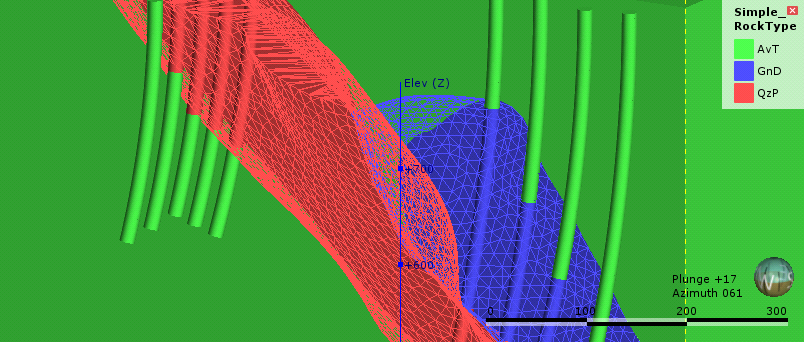
For both resolution settings above, the triangles are the same size everywhere in each surface, even where real data is available. Once the adaptive isosurfacer has been enabled, the triangles closer to the drillholes are smaller than those further away:
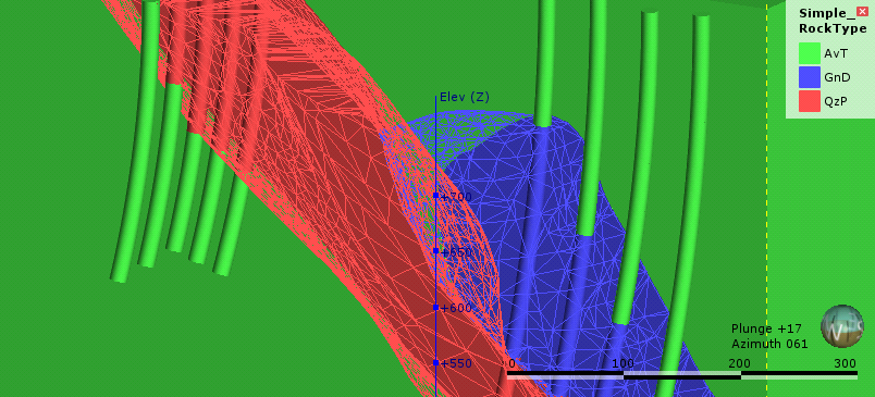
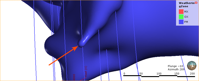
Areas of the surface that have large triangles indicate that there is less data in those areas to guide the interpolation of the surface.
In Leapfrog Geo, the resolution for different types of surfaces can be controlled as follows:
- For geological models, a resolution can be set for the model as a whole, but individual surfaces can have different settings. See Surface Resolution for a Geological Model.
- For interpolants, the resolution of the output isosurfaces is controlled by a single setting that can be overridden for individual surfaces.
- The resolution can be changed for editable interpolated meshes (
 ) and can be adaptive. See Interpolated Meshes.
 - When the topography has been defined using multiple data sources, the resolution can be set and the adaptive option is available. See Changing Topography Settings.
Adding Data to Surfaces
Select the type of data you wish to use to modify the surface. Leapfrog Geo will display all the suitable objects in the project. Select the required object and click OK. A hyperlink to the added data will appear under the surface in the project tree. The added data can be removed from the surface by expanding the surface in the project tree, then right-clicking on the hyperlinked data object and selecting Remove.
Honouring Surface Contacts
In Leapfrog Geo, surfaces can be created from drillhole data, points data, structural data, GIS data and polylines. When surfaces are created from several different objects, it may be desirable to snap the surface to some data objects but not to others.
There are several options for snapping surfaces to data:
- Off. The surface does not snap to the data used to create it.
- All data. The surface snaps to data within the Maximum snap distance, which includes drillhole data and any data added to the surface.
- Drilling only. The surface snaps to drillhole data and data objects derived from drillhole data within the Maximum snap distance but not to other data used to modify the surface. For example, the surface will honour points data derived from drillhole data, but not points data imported into the Points folder.
- Custom. The surface snaps to selected data objects within the Maximum snap distance.
Snapping forces surfaces to honour the specified contacts, moving triangles on the surface so that the surface precisely intersects the contact. For example, snapping is disabled for the surface on the left, but enabled for the surface on the right. The points used to generate the surface are shown in red, and the triangles are displayed so you can see how snapping to data affects the surface:
When snapping is enabled, the Maximum snap distance is used to determine what data should affect the surface. The Maximum snap distance is, by default, set to half of the Surface resolution setting, but you can adjust that up or down, if required.
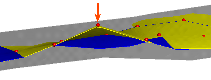
In this image, three surfaces are shown, along with the points used to generate the surface (red). The grey surface is the surface that results when snapping is Off. For the yellow surface, snapping to the points is enabled and the Maximum snap distance has been set to a high value, resulting in the yellow surface snapping to the distant point indicated by the arrow. Snapping to points is also enabled for the blue surface, but the Maximum snap distance has been set to a lower value, so that the surface snaps to some close points, but does not snap to the distant point.
While the most suitable snapping option is always project- and purpose-specific, if you have sufficient drilling data, snapping to Drilling only is recommended. This option gives the highest priority to the input data itself while still allowing the surface to be influenced by manual interpretations. Contrary to the All data snapping option, the Drilling only option also reduces the potential for complications resulting from contradictory data (e.g. the drilling data indicates a surface contact is in one place, but a polyline indicates it’s somewhere else).
Take care in enabling snapping and in selecting what data the surface will snap to, as the more data you include, e.g. by setting a large Maximum snap distance or selecting All data for Snap to data, the greater the possibility that errors in the data or assumptions inherent in interpretations (e.g. polylines) will cause distortions in the meshes. If you do enable snapping, it is best to snap only to drilling data.
For example, here the Snap to data has been set to Drilling only for a mesh created from multiple data objects:
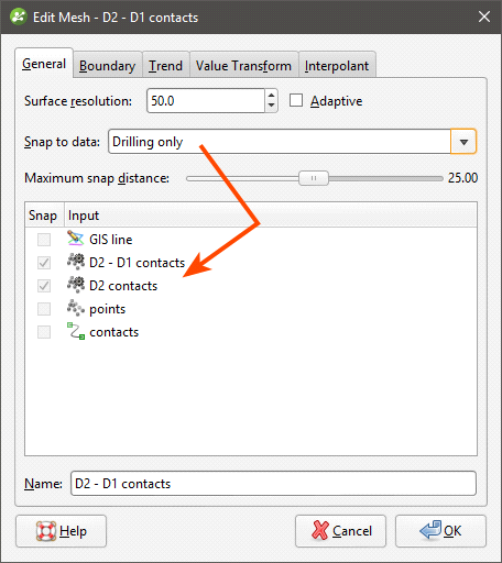
Note that the only objects Snap is enabled for are the contacts derived from drillhole data.
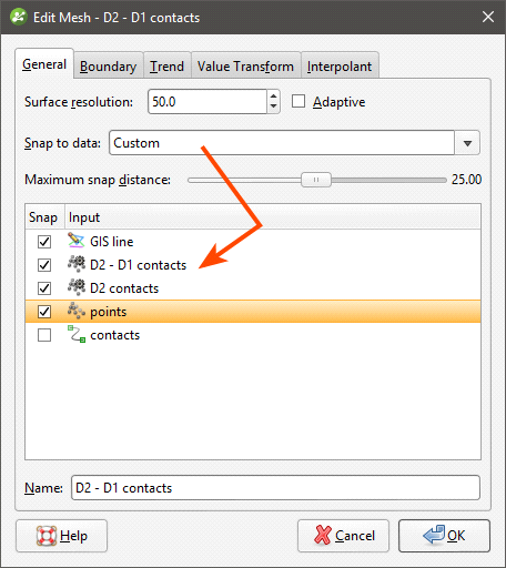
Here, Snap to data has been set to Custom, which makes it possible to enable Snap for only the selected data objects:
In Leapfrog Geo, the snap settings for different types of surfaces can be controlled as follows:
- For geological models, Snap to data can be set for the model as a whole, but individual surfaces can have different settings. For more information, see:
- For editable interpolated meshes and offset meshes (), Snap to data can be set by double-clicking on the mesh and changing the settings in the General tab. See Refining an Interpolated Mesh and Offset Meshes for more information.
Global Trends
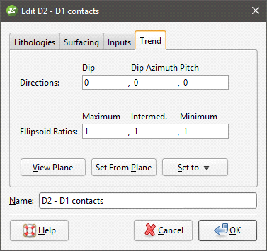
In Leapfrog Geo, many surfaces can be adjusted by applying a trend to the surface. To do this, add the surface you wish to adjust to the scene so that it can be used in setting the trend. Double-click on the surface in the project tree and select the Trend tab. Here, the Trend tab is displayed for a contact surface:
Often the easiest way to apply a trend is to click on the Draw plane line button (![]() ) and draw a plane line in the scene in the direction in which you wish to adjust the surface. You may need to rotate the scene to see the plane properly.
) and draw a plane line in the scene in the direction in which you wish to adjust the surface. You may need to rotate the scene to see the plane properly.
The Ellipsoid Ratios determine the relative shape and strength of the ellipsoids in the scene, where:
- The Maximum value is the relative strength in the direction of the green line on the moving plane.
- The Intermed. value is the relative strength in the direction perpendicular to the green line on the moving plane.
- The Minimum value is the relative strength in the direction orthogonal to the plane.
Once you have adjusted the plane to represent the trend you wish to use, click the Set From Plane button to copy the moving plane settings.
The Set to list contains a number of different options Leapfrog Geo has generated based on the data used in the project. Isotropic is the default option used when the surface was created. Settings made to other surfaces in the project will also be listed, which makes it easy to apply the same settings to many surfaces.
Click OK to apply the changes.
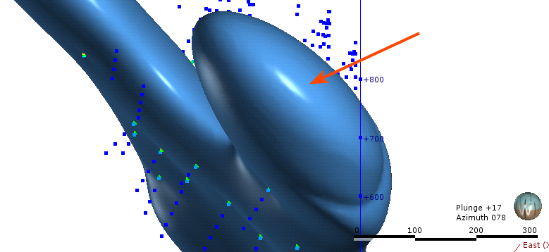
How the moving plane can be used to adjust a surface in this manner is illustrated by the following intrusive contact surface:
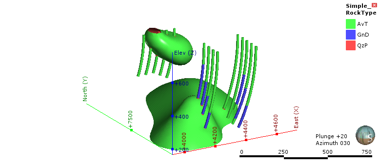
The intrusion surface has two bodies that are not connected, and we can apply a trend to connect the two parts. Here, the intrusion surface has been hidden in the scene and the scene rotated to line up the QzP segments. A plane line can then be drawn through the QzP segments:
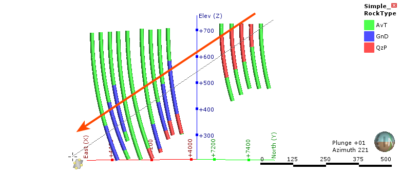
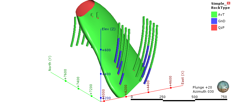
Using the plane settings to adjust the surface results in the two parts of the intrusion joining up:
Structural Trends
Structural trends create a flat ellipsoid anisotropy that varies in direction with its inputs. This topic describes working with structural trends. It is divided into:
Creating a Structural Trend
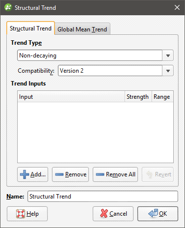
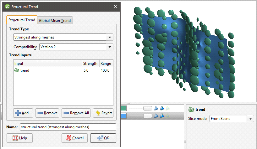
To create a new structural trend, right-click on the Structural Trends folder (in the Structural Modelling folder) and select New Structural Trend. The Structural Trend window will appear:
Structural trends can be created from surfaces and from structural data. Click Add to select from the suitable inputs available in the project. The list of inputs will be displayed:
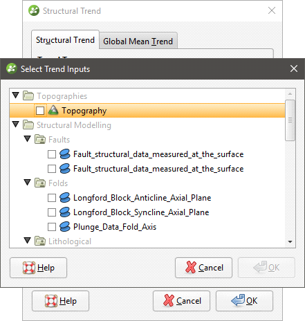
Tick the box for each input required, then click OK. The selected inputs will be added to the Structural Trend window:
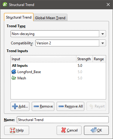
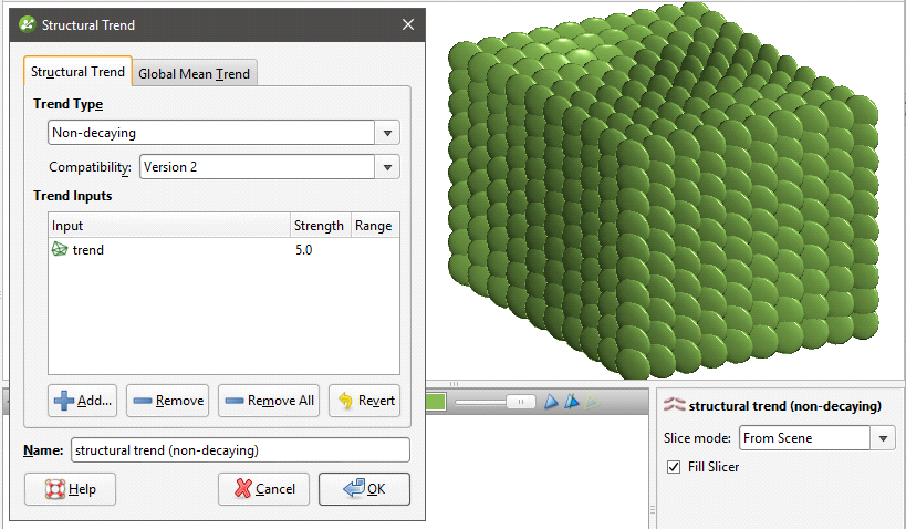
The Strength parameter determines the shape of the ellipsoid, and the Range parameter indicates how far the influence of this mesh reaches. If the Trend Type is Non-decaying, the distance from the mesh no longer affects the anisotropy and the Range value cannot be set.
Trends that are Strongest along meshes or Blending can include a global trend. To set this, click on the Global Mean Trend tab.
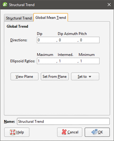
You can enter the trend manually or add the moving plane to the scene and set the trend using the moving plane, as described in Global Trends.
The Compatibility setting determines the algorithm used to create the structural trend. Structural trends created in earlier versions of Leapfrog Geo (before 2.2) used the Version 1 algorithm. When these structural trends are upgraded, you can change them so they use Version 2, which may be desirable if adding more data to the trend results in significant changes in areas that are not close to new data.
Enter a Name for the trend and click OK. The new trend will appear under the Structural Trends folder.
Displaying a Structural Trend
When displayed in the scene, the trend is shown using disks placed on a regular grid:
The orientation of the disk gives the direction of the anisotropy. The size of a disk is proportional to the anisotropy strength. Where there are no disks (or the size is very small) the trend is isotropic.
If the Trend Type is set to Non-decaying, the distance from the mesh no longer affects the anisotropy and all disks have the same size:
The Blending option requires multiple meshes and blends them according to their individual strength settings. A trend with higher strength makes a stronger impact on the blending. The blended trend is of decaying-type, and its strength weakens further away from the mesh.
Applying a Structural Trend
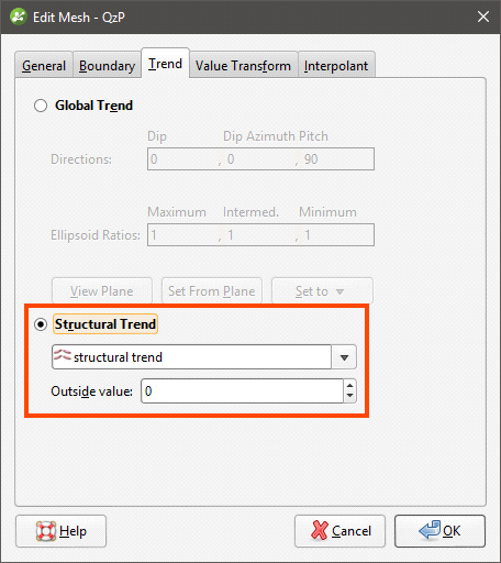
To apply a structural trend to an interpolated editable mesh or an interpolant, double-click on the object in the project tree and click on the Trend tab:
To apply a structural trend to an intrusion contact surface, enable Show additional surfacing options in the Surfacing tab, then click on the Trend tab.
Click on Structural Trend, then select the required trend from the list. Click OK to apply the trend to the surface.
When a structural trend is applied, surfaces may appear distorted further away from the data:
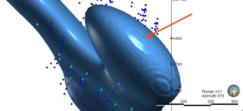
If this is the case, experiment with the Outside value setting. The Outside value is the long-range mean value of the data. Setting a value of -1 for intrusions (where the positive values are on the inside) and +1 for other surfaces will result in a smoother surface in most cases. For example, here, the Outside value has been set to -1 for this intrusion, resulting in a much smoother surface:
Editing Surfaces with Polylines
In Leapfrog Geo, many surfaces can be edited using polylines, including contact surfaces, geological model extents and editable meshes.
To edit a surface with a polyline, it is a good idea to first add the object you wish to edit to the scene and draw a slice across the scene where you plan to edit the surface. Next, right-click on the surface in the project tree and select Edit > With Polyline.
The drawing toolbar will appear for the type of polyline selected and a new polyline will be added to the scene. Draw the polyline and adjust it as described in Drawing in the Scene, then click the Save button (![]() ) to view the effect of the polyline on the surface. To remove the polyline from the surface, expand the surface in the project tree. Right-click on the polyline object and select Remove.
) to view the effect of the polyline on the surface. To remove the polyline from the surface, expand the surface in the project tree. Right-click on the polyline object and select Remove.
In cases where you have existing polyline edits (control points), you can import them and add them to the surface. To do this, import the polylines to the Polylines folder, then add them to the surface by right-clicking on the surface and selecting Add > Polyline.
How a polyline can be used to edit a surface can be illustrated by the following surface, where a small volume is disconnected from the main surface:
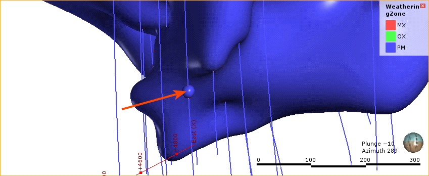
First, a slice is drawn through the surface where it will be edited:
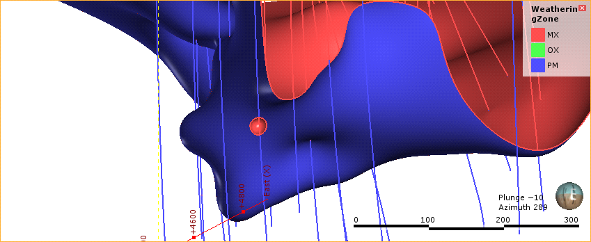
Next, a polyline is created, using two lines to represent contacts that link up the surfaces:
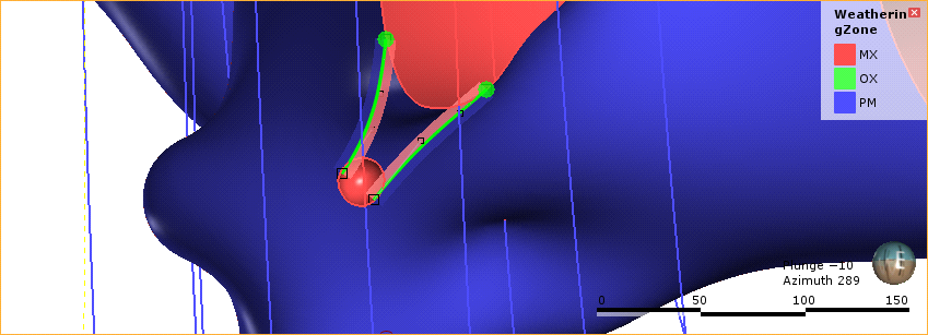
When the polyline edits are saved, the surface is updated to reflect the edits:
It is best to keep polyline edits to a minimum, as small edits can have significant effects on the shapes of surfaces.
If editing a surface with a polyline results in a distorted surface, use the surface and normal ribbons to check the orientation of the polyline and its segments. See Tangents and Ribbons for more information.
When you save the polyline, the object will be updated to reflect the additional points. The polyline will be added to the project tree as part of the object that was edited. You can edit the polyline by double-clicking on it or by right-clicking and selecting Edit Polyline.
Editing Surfaces with Structural Data
In Leapfrog Geo, many surfaces can be edited using planar structural data points drawn in the scene. Surfaces that can be edited in this way include contact surfaces, model extents and interpolated editable meshes. There are two ways to do this:
- If you have a structural data table created in or imported into Leapfrog Geo that you want to use to adjust the surface, right-click on the surface in the project tree and select Add > Structural Data. You will be prompted to select from the structural data tables available in the project.
- If you want to create structural data points to use to adjust the surface, right-click on the surface in the project tree and select Edit > With Structural Data.
To edit a surface with structural data using the second option, it is a good idea to first add the object you wish to edit to the scene. Next, right-click on the surface in the project tree and select the Edit > With Structural Data option.
The structural data toolbar will appear and a new structural data object will be added to the scene. Draw the structural data points and adjust them as described in Creating New Planar Structural Data Tables, then click the Save button (![]() ) to view the effect on the surface. Structural data tables created in this way cannot be used by other objects in the project until the table has been shared. To do this, right-click on the table in the project tree and select Share. The structural data table will be saved to the Structural Modelling folder.
) to view the effect on the surface. Structural data tables created in this way cannot be used by other objects in the project until the table has been shared. To do this, right-click on the table in the project tree and select Share. The structural data table will be saved to the Structural Modelling folder.
To remove the structural data from the surface, expand the surface in the project tree. Right-click on the structural data object and select Remove.
Got a question? Visit the My Leapfrog forums at https://forum.leapfrog3d.com/c/open-forum or technical support at http://www.leapfrog3d.com/contact/support