Extracting Points from Drillhole Data
This topic describes extracting different types of points from imported drillhole data. It is divided into:
- Extracting Contact Points from Drillhole Data
- Extracting Intrusion Values from Drillhole Data
- Extracting Interval Midpoints from Drillhole Data
If you wish to save and export points data with X-Y-Z information, use these options, then right-click on the data object to export the data as described in Exporting Points Data.
Extracting Contact Points from Drillhole Data
Contact points define the boundary between two lithology layers. You can extract contact points from interval tables to create a new points object in the Points folder. The values extracted are the x-y-z values of the contact points.
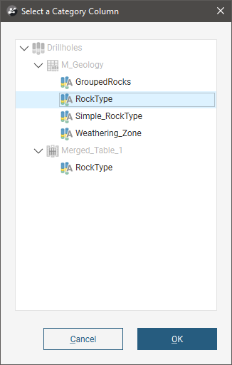
To extract contact points from an interval table, right-click on the Points folder and select New Contact Points. A window will appear listing the lithology and category columns available in the project:
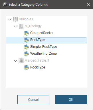
Select the required column and click OK.
Next, the New Contact Points window will appear:
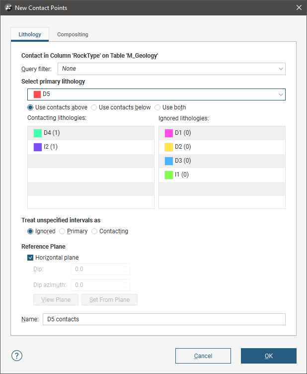
Select the lithology required from the Select primary lithology list, then select the adjacent lithologies you wish to extract in the Contacting lithologies list.
Unspecified intervals are intervals that have no data. By default, unspecified intervals are ignored when creating new contact points, but you can also treat them as the primary lithology or as contacting lithologies.
For complex geologies, the up and down directions for the surface may not be clear. If this is the case, untick the Horizontal Plane box. A reference plane will appear in the scene, with the up-facing surface labelled A and the downward-facing surface labelled B:
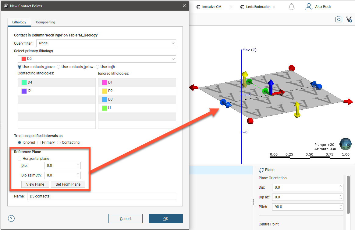
When you disable the Horizontal plane option for the Reference Surface, the number of contacts is longer displayed in the lithologies lists, as the number of contact points is not updated when the reference surface used changes.
Controlling the position of the reference plane is similar to controlling the position of the moving plane:
- Use the handles in the scene window to move the plane.
- Set the Dip and Dip Azimuth values in the New Contact Points window. The reference plane will be updated in the scene.
Once the reference plane is correctly oriented, click the Set From Plane button.
A reference plane set for contact points in the Points folder will be applied wherever the contact points are used.
Click OK to create the points, which will appear in the project tree under the Points folder. To edit the points, double-click on them.
Extracted contact points can be exported as described in Exporting Points Data.
Extracting Intrusion Values from Drillhole Data
You can extract intrusion points from interval tables to create a new points object in the Points folder.
To extract intrusion values from an interval table, right-click on the Points folder and select New Intrusion Values. A window will appear listing the lithology and category columns available in the project:
Select the required column and click OK.
Next, the New Intrusion window will appear:
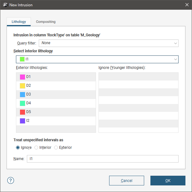
Select the intrusion lithology, then move any younger lithologies to the Ignore list.
Unspecified intervals are intervals that have no data. By default, unspecified intervals are ignored when extracting intrusion values, but you can also treat them as the interior lithology or as exterior lithologies.
The settings in the Compositing tab are described in Category Composites.
Click OK to create the new points object, which will appear in the project tree under the Points folder. To edit the points, double-click on the points object (![]() ) in the project tree. See Intrusion Point Generation Parameters below.
) in the project tree. See Intrusion Point Generation Parameters below.
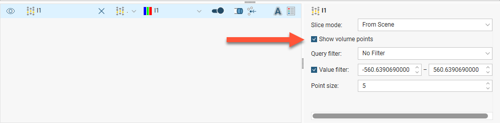
When you view the intrusion points in the scene, you can display only the contact points or all the points used determining the extrusion values. To display all points, click on the points object in the shape list and tick the box for Show volume points:
Extracted intrusion points and values can be exported as described in Exporting Points Data.
Intrusion Point Generation Parameters
To change the way intrusion values are generated, double-click on the points object in the project tree:
The Edit Intrusion window will appear, displaying the Point Generation tab.
Here, the surface and volume points are displayed to show the effects of the Surface offset distance and Background fill spacing parameters:
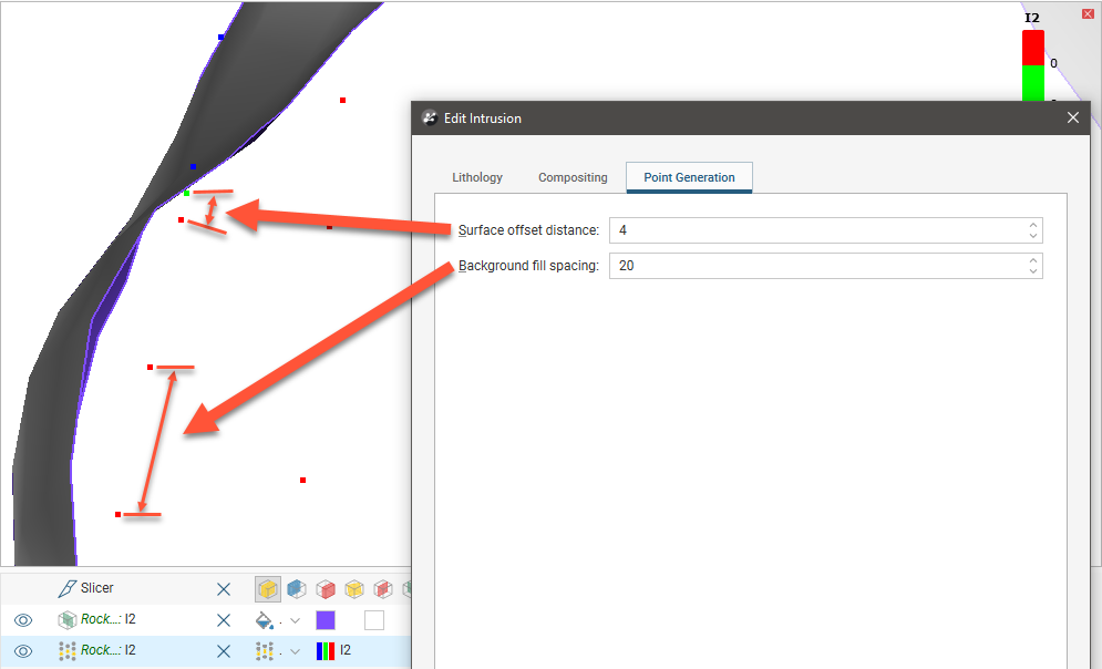
The Surface offset distance parameter sets the top and bottom ends of the interval and affects how a surface behaves when it approaches a contact point. A smaller distance restricts the angles that an approaching surface can take. Another factor that affects the angles a surface will take is whether or not a trend has been applied to the surface.
The Background Fill Spacing parameter determines the approximate length of segments in the remaining intervals. If the remaining interval is not a multiple of the Background Fill Spacing value, Leapfrog Geo will automatically adjust the spacing to an appropriate value. A smaller value for Background Fill Spacing means higher resolution and, therefore, slightly smoother surfaces. However, computation can take longer.
Extracting Interval Midpoints from Drillhole Data
You can extract interval midpoints from raw or composited numeric and category tables to create a new points object in the Points folder. The extracted points will be dynamically linked to the original drillhole segments and can be evaluated against other data in the project. The values extracted are the midpoints of each segment, the X-Y-Z values and the hole ID.
If you are exporting points data for use in Snowden Supervisor, use this option for extracting points from drillhole data. If you wish to export midpoints from an interpolant, see Exporting Numeric Model Midpoints.
To extract midpoints from an interval table, right-click on the Points folder and select New Interval Mid Points. In the window that appears, select the required Source table, then select which data columns to use:
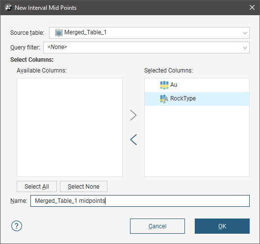
Apply a query filter, if required, then click OK. The new points object will appear in the project tree under the Points folder. To edit the points, double-click on the points object in the project tree.
Changes made to the source data table, such as changes to compositing parameters or special values rules, will be reflected in the extracted points object.
Extracted interval midpoints can be exported as described in Exporting Points Data.
Got a question? Visit the Seequent forums or Seequent support