Creating a 2D FEFLOW Model
A 2D FEFLOW model defines the block size, boundaries and surface features for a 3D FEFLOW model. Although existing 2D grids can be imported into Leapfrog Geothermal and used for creating 3D models, creating the 2D grid in Leapfrog Geothermal provides the most flexibility, as the block sizes can easily be changed, the boundaries modified and features added to provide finer resolution where there is more data available.
It is not necessary to create a geological model before creating a 2D grid. However, you will not be able to create a 3D grid until a geological model has been created. Therefore, it is a good idea to create the geological model first, and its dimensions can be used in defining the boundary of the 2D grid.
To create a 2D grid, right-click on the Flow Models folder and select FEFLOW > New 2D Model. The New 2D FEFLOW Grid window will appear:
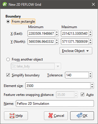
All settings can be changed once the grid has been created. It is, therefore, reasonable to accept the default settings and create the grid, then add it to the scene and begin refining it. Click OK to create the initial grid.
In the project tree, a 2D FEFLOW grid is made up of a grid object and a nodes object, as described in FEFLOW Model Display. Here, a newly-created grid with a rectangular boundary appears in the project tree:

Expand the grid in the project tree and double-click on the grid object (![]() ) to open the Edit 2D FEFLOW Grid window. The Features tab will be displayed. When a grid is first created, this window will be empty, but once features have been added, you can enable them in this tab.
) to open the Edit 2D FEFLOW Grid window. The Features tab will be displayed. When a grid is first created, this window will be empty, but once features have been added, you can enable them in this tab.
Click on the Boundary tab to modify the boundary:
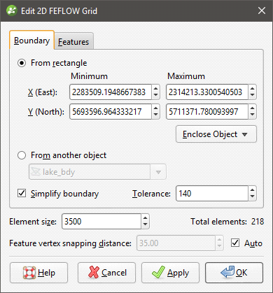
Click the Apply button to view the effect of changes made without closing this window.
Boundary Options
When setting the Boundary, you can set a rectangular boundary defined by the From rectangle settings. You can use the extents of any other object in the project by selecting from the Enclose Object list, but the grid boundary will always be a rectangle.
To define a non-rectangular boundary, use the From another object options and select from the list of objects available in the project. This is useful if, for example, you wish to define a grid using the boundary of a geological model.
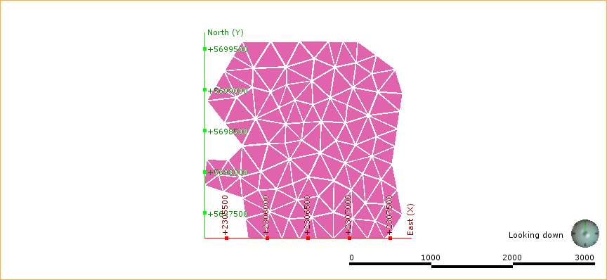
The Simplify boundary option reduces the number of points along the boundary. Reducing the Tolerance value increases the number of points along the boundary. The two settings together let you define a basic boundary with elements that are roughly uniform in size, set by the value of Element size. Here, a grid has been created from a geological model with the Simplify boundary option enabled:
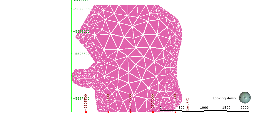
Disabling the Simplify boundary option results in more detail around the edges of the grid:
Element Size
The Element size setting determines the basic size of the triangles that make up the grid, although the size will vary according to features applied to the grid and the Feature vertex snapping distance. The size will also vary if the Simplify boundary option is unticked, in which case the Element size setting is the maximum size of the triangles.
The Feature vertex snapping distance is automatically set to 1 percent of the Element size. To use a smaller snapping distance, untick the Auto box and set the value required.
The effects of the Feature vertex snapping distance do not become apparent until features have been added to the grid.
Adding Features to the Grid
To add features to the grid, right-click on the grid in the project tree and select New Feature. The New FEFLOW Feature window will appear:
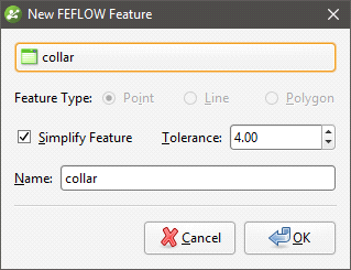
You can add Point, Line and Polygon features, and the Feature Object list will display all suitable objects available in the project. Ticking the Simplify Feature option will reduce the number of points used.
Click OK to add the feature, which will appear in the project tree under the FEFLOW grid object:
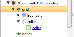
You can edit the feature by double-clicking on it or by right-clicking and selecting Open. However, the feature has not yet been applied to the grid. To enable the feature, double-click on the grid to open the Edit 2D FEFLOW Grid window. Tick the box to enable the feature, then adjust the number of Refinement Steps:
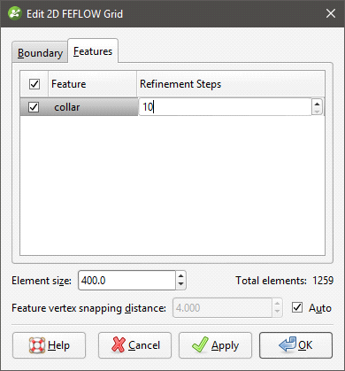
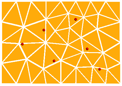
More Refinement Steps will produce more detail near the feature.
Click Apply or OK to view the effect the feature and its settings have on the grid.
If you want to modify a feature without having to reprocess the grid, untick it in the Features tab. If you want to delete a feature, right-click on it in the project tree and select Delete.
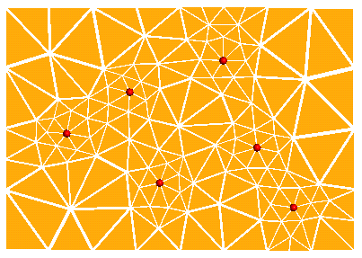
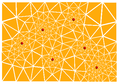
The images below show a grid displayed with collar points (in red) to demonstrate the effects of no features and collars applied with different refinement steps:
|
|
|
| No features | Collars with 2 refinement steps | Collars with 10 refinement steps |
To view all features added to a grid, right-click on the grid and select View Snapped Features. A Snapped Features object will appear in the shape list that represents all objects used to add features to the grid:
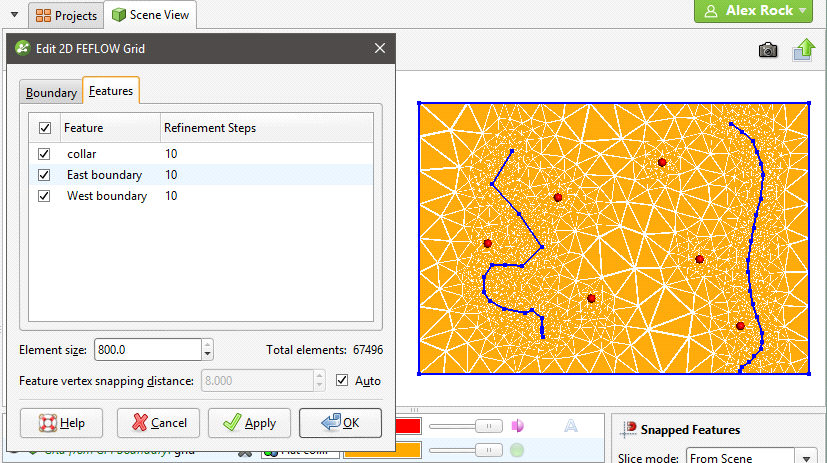
Here, four snapped objects appear in the scene: the three features listed in the Features tab and the grid’s boundary.
See Creating a 3D FEFLOW Model for information on using the 2D grid as the basis for a 3D model.
Got a question? Visit the Seequent forums or Seequent support