TOUGH2 Models
In Leapfrog Geothermal, you can create, import and visualise TOUGH2 simulations, inputs and outputs. You can also generate rocktypes, faulted and unfaulted, from a geological model or combined in the project and export block lithologies and TOUGH2 inputs. When creating TOUGH2 models in Leapfrog Geothermal, you can create structured or unstructured grids.
The rest of this topic describes working with TOUGH2 models in Leapfrog Geothermal. It is divided into:
- Structured TOUGH2 Models
- Unstructured TOUGH2 Models
- Importing TOUGH2 Models
- Displaying TOUGH2 Models
- Editing TOUGH2 Grid Parameters
- Editing Rock Type Properties
- Evaluating a Faulted Model
- Copying a TOUGH2 Model
- Creating a Static Copy of a TOUGH2 Model
- Exporting TOUGH2 Models
Structured TOUGH2 Models
To create a new structured TOUGH2 model, you must first have at least one geological model defined in the project.
To create a structured TOUGH2 model, right-click on the Flow Models folder and select TOUGH2 > New Structured Model. The New TOUGH2 Grid window will appear, together with controls in the scene that will help you define the model:
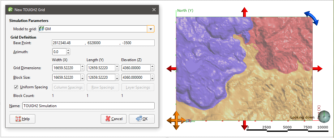
A geological model or a combined model can be used for the initial grid dimensions. Select the model required from the Model to grid list and set the dimensions of the grid.
Once you have created a new TOUGH2 model, you cannot change what model is used as the basis for the grid.
The scene will be updated to reflect changes you make in the New TOUGH2 Grid window.
The model should be slightly smaller than the selected model. Any TOUGH2 blocks that exist outside the model will be marked as inactive when the model is exported.
The default Block Count is 1x1x1. To use different block spacing, untick the Uniform Spacing box and then click the Spacings buttons to change the number of blocks. In the Edit Spacings window, you can select multiple spacings by holding down the Shift key while clicking on each item.
There are four ways to change the spacings:
- Click on a value to edit it.
- Divide a row or column. Click on a row or column, then on the Divide Row or Divide Column button. Two new rows or columns will appear in the list.
- Merge rows or columns. Hold down the Shift key while clicking on each item, then click on the Merge Rows or Merge Columns button. The selected items will be combined.
- Set uniform spacing on selected rows or columns. You will be prompted to enter the number of cells you wish to create from the selected rows or columns.
Click OK.
Here the Column Spacings have been set to 10 cells uniformly spaced:
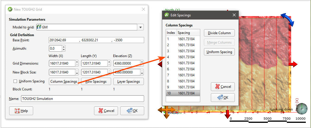
Click OK to create the model, which will appear in the project tree under the Flow Models folder. You can then change parameters for the model, load inputs and outputs, edit rocktype information and export block lithologies.
Unstructured TOUGH2 Models
To create a new unstructured TOUGH2 model, you must first have at least one geological model defined in the project.
To create an unstructured TOUGH2 model, right-click on the Flow Models folder and select TOUGH2 > New Unstructured Model. The New Unstructured TOUGH2 Model window will appear, together with controls in the scene that will help you define the top and depth of the grid:
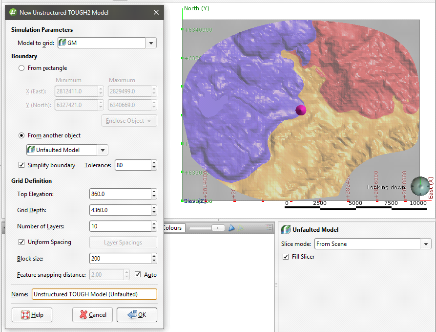
A geological model or a combined model can be used for the initial grid dimensions. Select the model required from the Model to grid list and set the dimensions of the grid.
Once you have created a new TOUGH2 model, you cannot change what model is used as the basis for the grid.
The Boundary can be rectangular or it can be defined from another object in the project.
The model should be slightly smaller than the selected model. Any TOUGH2 blocks that exist outside the model will be marked as inactive when the model is exported.
The Simplify boundary option reduces the number of points along the boundary. Reducing the Tolerance value increases the number of points along the boundary. The two settings together let you define a basic boundary with elements that are roughly uniform in size, set by the value of Block size. Once you have created the grid, you will be able to add features to it, which will change the size of the blocks.
Layers will be uniform, but if you want more control over the layers, untick the Uniform Spacing option and click Layer Spacings to set custom layers:
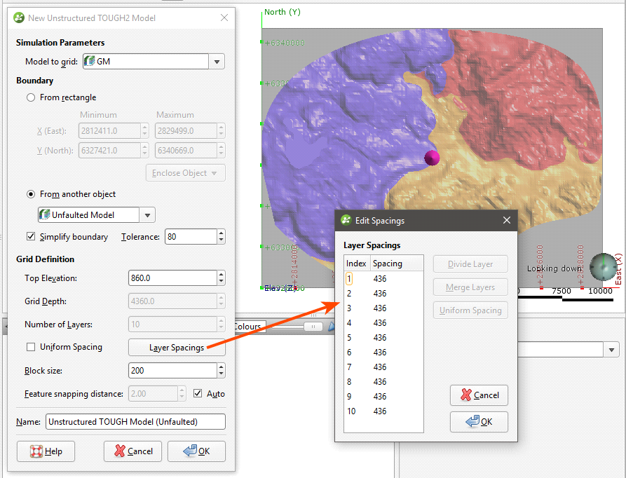
As with editing the spacings for a structured grid, there are four ways to change the spacings:
- Click on a value to edit it.
- Divide a row or column. Click on a row or column, then on the Divide Row or Divide Column button. Two new rows or columns will appear in the list.
- Merge rows or columns. Hold down the Shift key while clicking on each item, then click on the Merge Rows or Merge Columns button. The selected items will be combined.
- Set uniform spacing on selected rows or columns. You will be prompted to enter the number of cells you wish to create from the selected rows or columns.
The Block size setting determines the basic size of the blocks that make up the grid, although the size will vary according to features applied to the grid and the Feature snapping distance. The size will also vary if the Simplify boundary option is unticked, in which case the Block size setting is the maximum size of the blocks.
The Feature snapping distance is automatically set to 1 percent of the Block size. To use a smaller snapping distance, untick the Auto box and set the value required. You cannot set a value that is larger than 1 percent of the Block size.
The effects of the Feature snapping distance do not become apparent until features have been added to the grid.
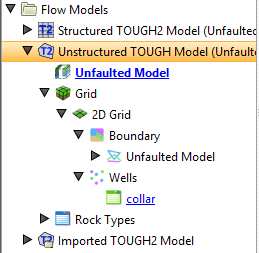
Click OK to create the model, which will appear in the project tree under the Flow Models folder:
Features can be points (![]() ), lines (
), lines (![]() ) or polygons (
) or polygons (![]() ).
).
Double-click on the 2D grid (![]() ) to see what features the grid has:
) to see what features the grid has:
When the model is created, the well collars are added to the model as a feature. When a faulted geological model used to define the model, the geological model’s faults will be included on the grid as features.
Double-click on the wells object in the project tree to view the individual wells:
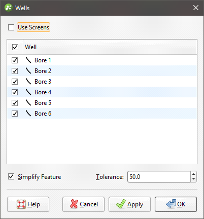
Untick any wells you do not want to use for defining the grid.
If screens are included in the well data, there will be a Use Screens option. When enabled, the x-y coordinates of the mid-point of the screen intervals will be used for the centre points. Otherwise, the x-y coordinates of the collar will be used.
Double-click on individual faults to change their settings.
To add features to the grid, right-click on the 2D grid (![]() ) in the project tree and select New Feature:
) in the project tree and select New Feature:
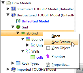
The New TOUGH2 Feature window will appear:
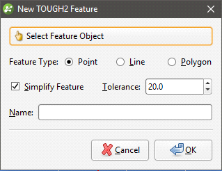
Click Select Feature Object to choose from suitable objects in the project. You can add Point, Line and Polygon features. Ticking the Simplify Feature option will reduce the number of points used.
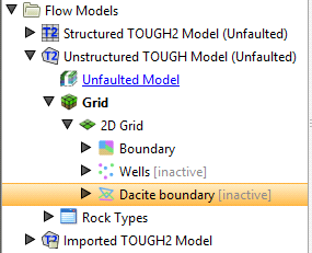
Click OK to add the feature, which will appear in the project tree under the TOUGH2 grid object:
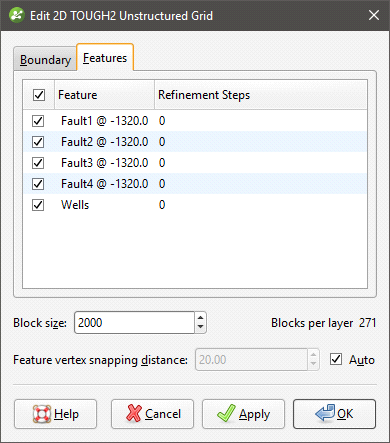
You can edit the feature by double-clicking on it or by right-clicking and selecting Open. However, the feature has not yet been applied to the grid. To enable the feature, double-click on the grid to open the Edit 2D TOUGH2 Unstructured Grid window. Tick the box to enable the feature, then adjust the number of Refinement Steps:
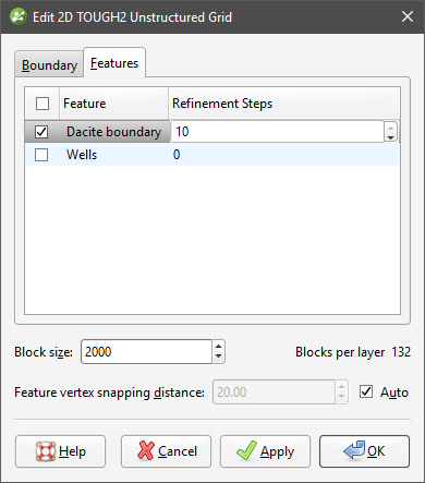
More Refinement Steps will produce more detail near the feature.
Click Apply or OK to view the effect the feature and its settings have on the grid.
If you want to modify a feature without having to reprocess the grid, untick it in the Features tab. If you want to delete a feature, right-click on it in the project tree and select Delete.
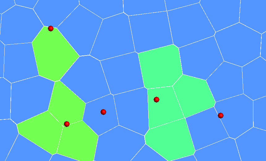
The images below show a grid displayed with collar points (in red) to demonstrate the effects of no features and collars applied with different refinement steps:
|
|

|
| No features | Collars with 2 refinement steps | Collars with 10 refinement steps |
Importing TOUGH2 Models
You can import structured and unstructured TOUGH2 models into Leapfrog Geothermal. The process for each type is the same. Right-click on the Flow Models folder and select TOUGH2 > Import Model. Leapfrog Geothermal will ask you to specify the file location. Click Open to import the file.
The TOUGH2 model will appear in the project tree under the Flow Models folder. You can then load TOUGH2 inputs and outputs and generate rocktypes.
Loading TOUGH2 Outputs
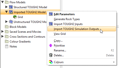
To import the outputs, right-click on the model in the project tree and select Import TOUGH2 Simulation Outputs:
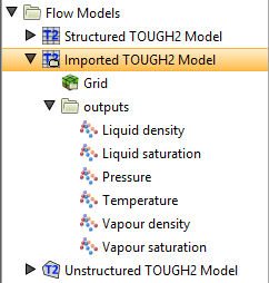
Navigate to the required file and click Open. The information will be added to the model and will appear in the project tree in a folder underneath the model:
The outputs can be visualised as described in Displaying TOUGH2 Models below.
Loading TOUGH2 Inputs
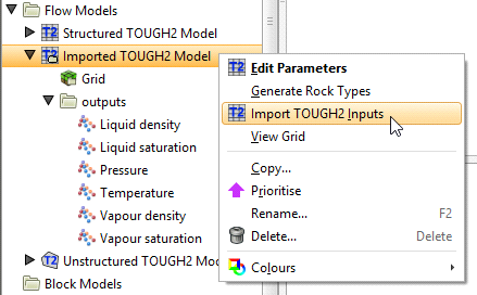
If you have imported a TOUGH2 grid, you can load the model inputs. To do this, right-click on the model in the project tree and select Import TOUGH2 Inputs:
Select the inputs file and click Open. The information will be added to the TOUGH2 model and can be visualised as described in Displaying TOUGH2 Models below.
You can delete the inputs by right-clicking on the model in the project tree and selecting Delete TOUGH2 Inputs.
Generating Rocktypes
If you have not loaded inputs onto an imported TOUGH2 model, you can generate rocktypes by evaluating a geological model or combined in the project onto the TOUGH2 grid. To do this, right-click on the model in the project tree and select Generate Rock Types:

The list of models available in the project will be displayed. Select the required model, then click OK. The information will be added to the model and will appear in the project tree as part of the model:

The rock types will be available as a colour option in the shape list when you display the model in the scene.
Displaying TOUGH2 Models
Display a TOUGH2 model by dragging it into the scene:
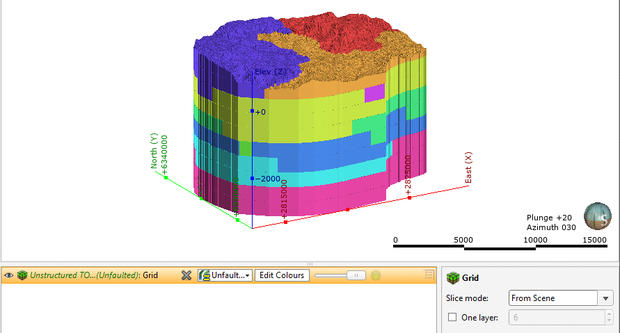
You can display the model as blocks or points, and you can display all layers or only one layer:

You can select any input as a colour option in the shape list. If the input is time-dependent, a timestep slider will be available from the shape properties panel:
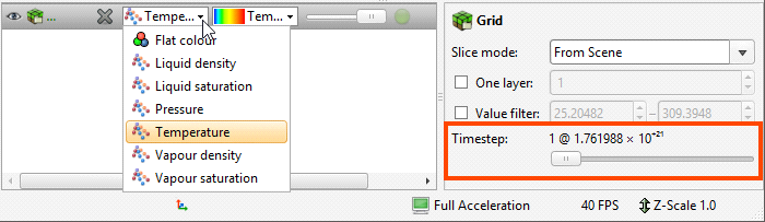
Click and drag the slider or click along the timeline to view the different timesteps available.
Editing TOUGH2 Grid Parameters
Once you have imported or created a TOUGH2 grid, you can edit information about the grid by double-clicking on the grid in the project tree or by right-clicking and selecting Edit Parameters. The Edit TOUGH2 Simulation Model Parameters window will appear:
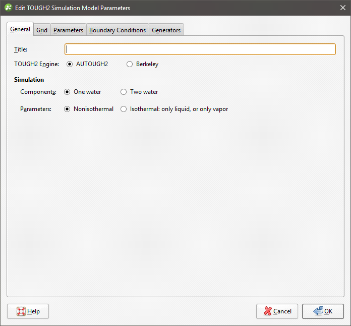
Select the TOUGH2 Engine used and set the simulation parameters. When the Two water component is selected, a Mass Fraction option is available when setting rocktypes for the simulation. See Generating Rocktypes for more information.
Note that if you select Two water, only the Nonisothermal option is available.
The Grid tab displays information about the grid definition.
In the other tabs, you can set TOUGH2 parameters and boundaries and define generators based on screens.
Generators can only be defined for structured models.
Once you have set all parameters required, click OK to save the changes.
TOUGH2 Parameters
The Parameters tab is divided into a number of sub-tabs along the left-hand side of the window:
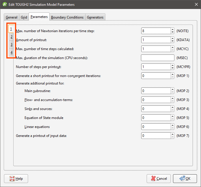
A negative value must be set for the Length of time steps (DELTEN) field before the Duration of timestep (DLT) fields can be set.
Once you have set the model parameters, click OK to make the changes.
TOUGH2 Boundary Conditions
Edit TOUGH2 boundary conditions by double-clicking on the model in the project tree, then selecting the Boundary Conditions tab:
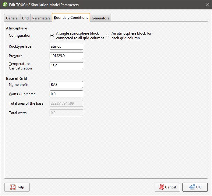
For Atmosphere, you can choose between:
- A single block that forms the top of all the grid columns
- Individual atmosphere blocks for each grid column
The Pressure and Temperature Gas Saturation units are kPa.
TOUGH2 Generators
If well data in the project includes a screens table, you can define generators for a structured TOUGH2 grid using the screens. To do this, double-click on the model in the project tree, then select the Generators tab:
In defining generators, it is important that the screens are correct and related to the wells; any errors in the screens table should be corrected before generators are defined.
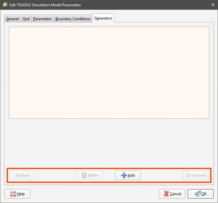
If the Add button at the bottom of the screen is greyed out, check that your screens table has been imported and that all errors in the table have been corrected.
Click the Add button to add a generator, then select the well required from the Screen list:
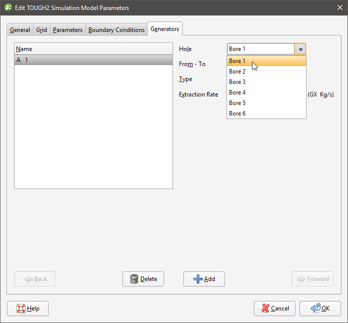
The From - To list displays the depths available for the selected well.
Select whether the Type is Extraction, Injection or Heat. Enter the properties required for each Type.
You can delete any generator by clicking on it in the table and selecting Delete.
Editing Rock Type Properties
To edit rock type properties for a TOUGH2 model, expand the model in the project tree and double-click on the rocktype object. The Edit Rock Type Properties window will appear:

The window above shows properties for an unfaulted model. See Evaluating a Faulted Model for information on editing rock type properties for a faulted model.
Note that the NAD property is read-only and locked to zero.
The Mass fraction of water 2 option can only be set for Two water simulations. See TOUGH2 Parameters for more information.
Evaluating a Faulted Model
A faulted rocktype evaluation is based on the fault system of the model associated with the TOUGH2 model. For TOUGH2 models created in Leapfrog Geothermal, the faulted rocktype evaluation is automatically created when the TOUGH2 model is defined; for imported TOUGH2 models, the evaluation is created when rocktypes are generated for the model.
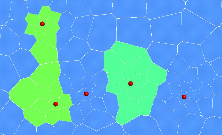
Each fault is assigned its own lithology value and if more than one fault intersects a block, a combination lithology is created. This grid shows two intersecting faults (purple) evaluated on the grid; all geological model blocks in this image are set to display in green. There are three faulted lithologies, one for each fault and one for the blocks where the two faults intersect:

In the project tree, the Fault Rock Evaluation appears under the Rock Types table. You can change which of the model’s faults are evaluated by double-clicking on the Fault Rock Evaluation and disabling faults:

The Thickness value represents the width of the fault’s crush zone. It is a distance value, and blocks within that distance are assigned the fault lithology. The default value is 0, which means that only blocks intersected by the fault will be assigned the fault lithology.
You can also change the evaluation names in this window; simply double-click on the name and edit the text. It is recommended that you keep evaluation names shorter than 10 characters.
Fault lithologies are separated from the model’s lithological units in the rock type table:

Copying a TOUGH2 Model
You can copy TOUGH2 models by right-clicking on them and selecting Copy. Enter a name for the copy of the model and click OK. The copy will be added to the project tree.
Creating a Static Copy of a TOUGH2 Model
You can create static copies of TOUGH2 models created in Leapfrog Geothermal. To do this, , right-click on the model in the project tree and select Static Copy. Enter a name for the copy of the model and click OK. The copy will be added to the Flow Models folder.
The grid geometry in a static TOUGH2 model cannot be changed. However, if the model associated with the TOUGH2 model is modified, the rock type table and the assignment of rock types to the grid blocks will be updated.
Exporting TOUGH2 Models
You can export the model inputs and the block lithologies.
Exporting Block Lithologies
To export block lithologies from a TOUGH2 model, you must first associate the model with a geological model or a combined model. See Generating Rocktypes for more information.
To export block lithologies, right-click on the table object (![]() ) underneath the TOUGH2 simulation and select Export Block Lithologies. Leapfrog Geothermal will ask you to specify the file location. You will then be prompted for an output filename. Enter a name and click OK.
) underneath the TOUGH2 simulation and select Export Block Lithologies. Leapfrog Geothermal will ask you to specify the file location. You will then be prompted for an output filename. Enter a name and click OK.
Exporting TOUGH2 Inputs
To export TOUGH2 inputs from a TOUGH2 model, you must first associate the model with a geological model or a combined model. See Generating Rocktypes for more information.
When you export a TOUGH2 grid, two files are saved:
- The *.DAT file is the TOUGH2 inputs.
- The *_geometry.DAT file is the grid definition.
To export inputs, right-click on simulation in the project tree and select Export TOUGH2 Input. Leapfrog Geothermal will ask you to specify the file location. You will then be prompted for an output filename. Enter a name and click OK.
Got a question? Visit the My Leapfrog forums at https://forum.leapfrog3d.com/c/open-forum or technical support at http://www.leapfrog3d.com/contact/support