Distance Functions
A distance function calculates the distance to a set of points. This topic describes how to create and modify distance functions. It is divided into:
Creating a Distance Function
To create a distance function, right-click on the Numeric Models folder and select New Distance Function. The New Distance Function window will be displayed:
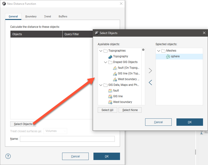
Click Select objects to choose from the objects available in the project. For wells, points, GIS points and imported GIS lines, you can apply any filter that has been defined for that object.
If any of the objects selected are closed surfaces, you can choose whether these surfaces are treated as Volumes or as Surfaces.
- When treated as Volumes, buffers will be generated only on the outside of the mesh. If the mesh is inverted, buffers will appear on its inner surface.
- When treated as Surfaces, buffers will be generated on both sides of the mesh.
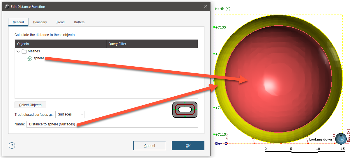
For example, here a distance function has been created using a sphere and one isosurface set to 2. The inner surface of the sphere is red, indicating that it is the inside of the mesh. The sphere is treated as a volume and there is a single isosurface (yellow) outside of the sphere:
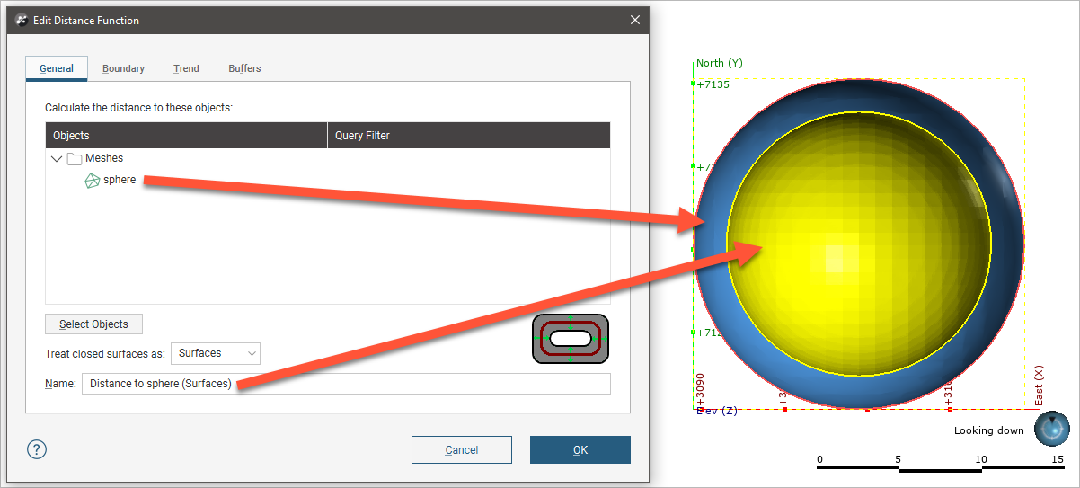
When the orientation of the sphere is reversed, indicated by the blue inside of the sphere, the isosurface (yellow) is generated on the inner surface of the sphere:
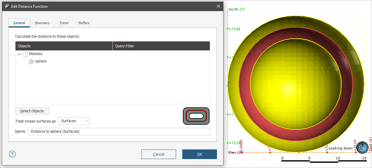
However, when the sphere is treated as a surface rather than as a volume, isosurfaces are generated on both sides of the sphere:
If you are unsure of some settings, most can be changed later. For a basic distance function click Select Objects to select from the suitable objects available in the project, then click on the Buffers tab to define at least one buffer so that the distance function can be visualised in the scene.
See:
Setting the Boundary
In the Boundary tab, you can set whether the function boundary is clipped or unclipped. No distance buffer clipping is the default setting, but if you choose to clip the buffers, you can choose between:
- Sharing another object’s extents
- Defining a set of extents that is independent of other objects in the project.
When you select the Shared with option, the distance function will be updated when the extents object it shares is updated.
Setting a Trend
In the Trend tab, you can set a trend using the moving plane or by entering the required values. You can also use the Set to list to choose different options used in the project. Isotropic is the default option used when the function is created.
The Ellipsoid Ratios determine the relative shape and strength of the ellipsoids in the scene, where:
- The Maximum value is the relative strength in the direction of the green line on the moving plane.
- The Intermed. value is the relative strength in the direction perpendicular to the green line on the moving plane.
- The Minimum value is the relative strength in the direction orthogonal to the plane.
Adding Buffers
To add buffers, click on the Buffers tab, then click the Add button:
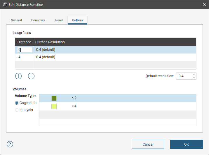
Enter the required value. To delete a buffer, click on it in the list, then click the Remove button. You can also change the colours used to display the buffers by clicking on the colour chips.
There are two options for Volume Type that affect how the buffers are calculated when more than one buffer is used. Selecting Concentric produces higher distance buffers that include the lower distance buffers, whereas selecting Intervals produces discrete, non-intersecting buffers.
The Default resolution setting is used for all new buffers and for existing buffers that use the default resolution.
The New Distance Function in the Project Tree
Click OK to create the distance function, which will be added to the Numeric Models folder. The new distance function contains objects representing different parts of the function, which can be expanded to show the inputs to each part of the function:
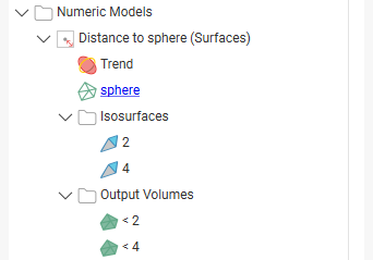
- The Trend object that describes the trend applied.
- Hyperlinks to objects used for the distance function.
- An Isosurfaces folder that contains all the meshes generated in building the distance function.
- An Output Volumes folder that contains all the distance buffer meshes.
Other objects may appear in the project tree under the function as you make changes to it.
Display the function by dragging it into the scene or by right-clicking on it and selecting View Buffers.
Once you have created a distance function, you can adjust its properties by double-clicking on it. You can also double-click on the individual objects that make up the function.
Got a question? Visit the Seequent forums or Seequent support