
Remove Data Discontinuities
Use the Remove Data Discontinuities option (geogxnet.dll(Geosoft.GX.UAVSurvey.RemoveDiscontinuities;Run)*) from the UAV Merge Sorties > Pre-processing menu to remove jumps in the data.
Remove Data Discontinuities dialog options
|
Input channel |
Select from the list, the channel manifesting discontinuities. Script Parameter: PLAN_UAV_SURVEY.REMOVE_DISCONTINUITY_INPUT |
|
Minimum discontinuity |
Define the magnitude of the smallest jump you would like to correct for. Click on Script Parameter: PLAN_UAV_SURVEY.MINIMUM_DISCONTINUITY |
|
Over a distance of |
Define the physical distance over which the discontinuity occurs. Script Parameter: PLAN_UAV_SURVEY.MINIMUM_DISCONTINUITY_DISTANCE |
|
Output channel |
Specify the output channel to contain the corrected data. Script Parameter: PLAN_UAV_SURVEY.REMOVE_DISCONTINUITY_OUTPUT |
|
Filter method |
Once a shifted segment is identified, you have a few options on how to rectify it:
Script Parameter: PLAN_UAV_SURVEY.REMOVE_DISCONTINUITY_FILTER
See the Application Notes for illustrations. |
 to calculate a default discontinuity value. The default data discontinuity is set to 20% of the standard deviation calculated on the selected data.
Application Notes
This correction should be applied after masking data acquired in turnarounds or while the system was stationary.
Some recording systems (e.g., GEM GSMP Potassium Magnetometer) inherently manifest systematic (and usually abrupt) jumps in the data. These jumps or discontinuities can be raised or lowered to match the main signal.
To locate the jumps, first, the difference between successive points is calculated. If the difference is more than the specified amount, a search for the next jump is initiated. Once a shifted segment is identified, the available correction options are:
- The entire section is lowered/raised by a calculated constant shift. This is the average of the two differences at the two ends of the jump.
- The entire section is lowered/raised by a 1st order shift. This is the equation of a straight line joining the two points at the two ends of the jump.
- The identified segment (that is higher or lower than the rest of the data) is removed and the gap is splined through (simple linear interpolation using the point before and after the discontinuity).
- The identified segment is simply dummied out.
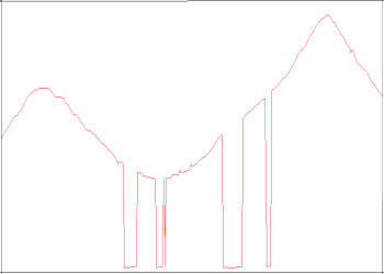
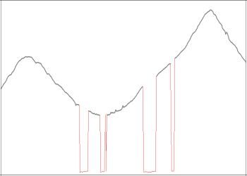
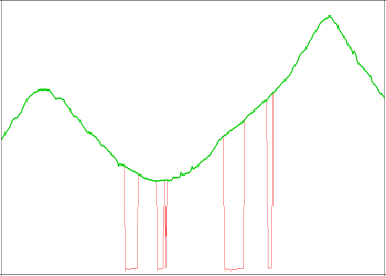
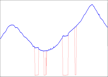
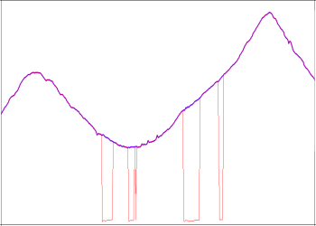
The illustrations below intend to display the character of each of the options:
|
Figure 1.1: Original signal |
Figure 1.2: In the simplest case, the discontinuous data segments can be dummied out. |
|
|
|
|
Figure 1.3: The discontinuous segments can be dummied out and splined through. |
Figure 1.4: The discontinuous segments can be DC shifted to the level of the main signal. |
|
Figure 1.5: A first order trend can be applied to shift each discontinuous segment. |
*The GX tool will search in the "...\Geosoft\Desktop Applications \gx" folder. The GX.Net tools, however, are embedded in the geogxnet.dll located in the "...\Geosoft\Desktop Applications \bin" folder. If running this GX interactively, bypassing the menu, first change the folder to point to the "bin" folder, then supply the GX.Net tool in the specified format.
See Also:
Got a question? Visit the Seequent forums or Seequent support
© 2023 Seequent, The Bentley Subsurface Company
Privacy | Terms of Use