
Voxels to Vector Voxel
Use the Voxels to Vector Voxel option (geogxnet.dll(Geosoft.GX.VoxUtils.ConvertVoxelsToVectorVoxel;Run)*) from the Voxel > Conversions menu, to assemble 3 voxel files into a Vector Voxel model.
Voxels to Vector Voxel dialog options
 Cartesian
 Rotated
 Inclination (degrees)
Application Notes
A vector voxel is a voxel model represented by 3 scalar values at each voxel point. These values define the 3 scalar components of a vector. A vector voxel model is displayed in the 3D viewer with directional arrows; the size and colour of which are indicative of the magnitude.
A vector voxel can be assembled from its 3 components in the standard Cartesian coordinate system, or a rotated coordinate system. In the standard Cartesian coordinate system, the scalar components are denoted as the X, Y, & Z component voxels. The X component is analogous to Easting, the Y component analogous to Northing and the Z component direction is upwards positive. In the rotated coordinate system, the projected components are denoted as U, V, & W. The U component is positive in the direction of the specified inclination and declination, the V and W components are perpendicular to each other and to U.
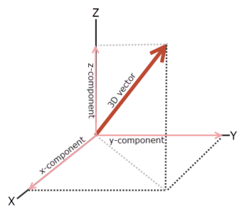
Figure 1: 3D Vector displayed with respect to Cartesian coordinates; Z is upwards positive.
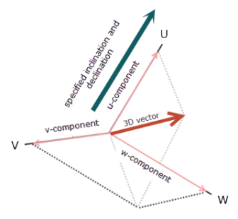
Figure 2: 3D vector displayed with respect to rotated coordinates; U is positive in the direction of the specified inclination and declination.
If a 3D Viewer is open when running the conversion, the output vector voxel will be displayed in the 3D Viewer window. Otherwise, the output voxel will be displayed into a new Voxel Viewer window. If the output voxel does not display, open the 'Advanced Settings' dialog (Project > Settings > Advanced) and under the Voxel Settings section, check if the 'Display Created Voxels' option is set to "True".
*The GX tool will search in the "...\Geosoft\Desktop Applications \gx" folder. The GX.Net tools, however, are embedded in the geogxnet.dll located in the "...\Geosoft\Desktop Applications \bin" folder. If running this GX interactively, bypassing the menu, first change the folder to point to the "bin" folder, then supply the GX.Net tool in the specified format.
Got a question? Visit the Seequent forums or Seequent support
© 2023 Seequent, The Bentley Subsurface Company
Privacy | Terms of Use