
Reject Coincident Tx-Rx
In an IP database, a reading may be taken when the transmitter (Tx) locations coincide with the receiver (Rx) locations. Allow rejecting (turning off) all readings for which the transmitter pair coincides exactly with the receiver pair. These readings will only contain noise. Similarly, reject readings for when a transmitter is located between the line joining the two receivers.
Reject Coincident Tx-Rx dialog options
Application Notes
If one or two Txs are situated within the area bound by the rectangle of width d (1/2 offset distance) around the Rxs, the corresponding readings should be rejected () because the current distribution around the transmitters is not uniform. This situation is sometimes encountered in 3D IP surveys ().
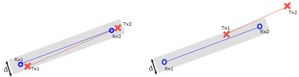
Figure 1.1: If Txs are located within the area of the grey rectangle 2 x offset-distance(Rx-spacing +1), the resulting readings should be rejected. Left: Plan view of coincident Txs & Rxs. Right: Plan view of a Tx situated between the two Rxs.
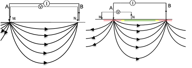
Figure 1.2: Section view of the propagation of the electric field around the Txs in a homogeneous half space. Data collected in the Red zone should be rejected.
Display Electrodes on Map
Any coincident electrodes will be displayed as filled grey symbols and connected with a dashed line:
- Dipole-Dipole: the 2 Txs & 2 Rxs are connected with dashed grey lines; the midpoints (Rx to Tx) are connected as well.
- Pole-Dipole: the 2 Rxs are connected with a dashed grey line; a dashed line from the Rx midpoint to the Tx is drawn.
- Pole-Pole: Tx & Rx are connected with a dashed grey line.
If a transmitter is between 2 receivers, all 3 or 4 electrodes will be displayed with the same size and filled grey symbols. The Txs will be connected with a dotted grey line.
Distant electrodes (i.e., the Tx separation > 10 * Rx separation) will not be joined.
Got a question? Visit the Seequent forums or Seequent support
© 2023 Seequent, The Bentley Subsurface Company
Privacy | Terms of Use