
Gradient Enhanced Gridding
The Gradient Enhanced Gridding dialog appears if you have selected "Yes" in response to the "Do you have gradient data?" prompt in the Advanced Gridding Options dialog.
Refer to the Application Notes below for additional information on gridding with gradient data.
Gradient Enhanced Gridding dialog options
Application Notes
Gridding without the cross-line gradient will interpolate the smoothest surface that honors the data along each line. Gridding with the cross-line gradient will produce a surface that both honors the data and the measured gradient at each line. This can produce very much-improved gridded surfaces, especially for features that approach the line separation in size.
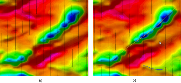
Figure 1: Gridded magnetic data: a) without cross-line gradient; b) with cross-line gradient enhancement.
The gradient enhanced method implemented in bigrid is the pseudo-line gridding method developed by Hardwick 1.
Although gridding with gradients will work with any type of data, the principle application is in the preparation of grids from aeromagnetic surveys that use two wing-tip sensors to measure the transverse gradient. The technique used in BIGRID uses both the measured total field data and the gradients to model the magnetic field over the grid area. This requires that both the total field and the gradient data be well leveled using conventional leveling techniques. This method also ensures accurate resolution of low-amplitude, long-wavelength features in the data, which are poorly resolved in the gradient measurements alone.
Following are potential sources of error when working with gradient data.
-
Aircraft orientation error. Because of the orientation of the survey aircraft in flight, gradients may not be measured on a true horizontal plane. However, provided the survey is conducted to minimize aircraft maneuver, this noise is normally minimal.
-
Aircraft control surface error. The simple movement of the aircraft control surfaces – notably the ailerons, can introduce magnetic noise to wing-tip sensors. Surveys should be flown with this in mind, and survey pilots should be more concerned with minimizing the use of ailerons over attempting to maintain a very accurate flight path and elevation. Low-pass filters can be used to remove aileron noise if necessary, though this noise often overlaps signal of interest, so such data will be degraded.
-
Actual horizontal gradients can be very small, often less than the noise level in the measured gradient. If long-wavelength, low-amplitude features are of interest, you should specify the noise level of the gradient data so that this information can be accurately recovered from the total field data.
-
Gradient data that is not properly compensated for aircraft orientation, notably for heading error, can contain base level differences that vary relative to the line direction. In this case, the measured gradient data can be corrected so that the mean matches the mean of the calculated gradient along each line. This should only be done if the data has not been properly compensated as this technique may introduce noise where the calculated gradient is inaccurate.
References
- C.D.Hardwick, "Gradient-enhanced total field gridding", SEG Technical Program Expanded Abstracts, 1999.
Got a question? Visit the Seequent forums or Seequent support
© 2023 Seequent, The Bentley Subsurface Company
Privacy | Terms of Use