
Multi-trend Gridding Advanced Options (Multiple Channels)
Use the Multi-trend Gridding Advanced Options dialog (geogxnet.dll(Geosoft.GX.GridUtils.NSIGriddingAdvancedOptions;Run)*) to specify advanced Multi-trend gridding options. This gridding method should be used with the distance units in ground coordinates. If your data is in geographic coordinates, project it to ground coordinates prior to running multi-trend gridding.
Multi-trend Gridding Advanced Options
|
Blanking distance |
All grid cells within this distance will be evaluated. All grid cells farther than the blanking distance from a valid point will be set to dummies in the output grid. If left empty, the blanking distance is set to 10 times the grid cell size. Script Parameter: NSI_GRIDDING.INTERP_DISTANCE |
|
Maximum iterations |
The maximum number of iterations after which the gridding process stops. Select a value between 0 and 100. By default, the number of maximum iterations is set to 50. Script Parameter: NSI_GRIDDING.MAX_ITER |
|
Trending factor |
The higher the trending factor, the smoother the lineaments will be. Select a value between 0 and 100. By default, the trending factor is set to 100. Script Parameter: NSI_GRIDDING.TRENDING_FACTOR |
|
Theta |
The increment in degrees (between 1 and 90) by which to rotate the trend direction, in order to have an adequate number of survey points within the search radius for calculating the grid value at the centre of the search circle. The trend direction is rotated in the CW (clockwise) direction. See the Application Notes below for more details. The default is set to 10. Script Parameter: NSI_GRIDDING.THETA |
|
[Reset] |
Click this button to restore the gridding parameters to their default values. |
Application Notes
Theta
In Figure 1 below, the original trend direction, determined by the structure tensor, is shown as an orange line. If it does not intercept real data within the search radius, the angle is changed by Theta (red solid line), and the search for real data is attempted again.
It is recommended to set the angle relatively small but greater than 0° not to deviate from the trend direction determined by the structure. On the other hand, a very small angle may increase the number of iterations and make the gridding process slower.
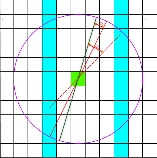
Figure 1: The blue cells contain real data; the green cell is the cell being analyzed; the purple circle is the search radius distance variable.
*The GX tool will search in the "...\Geosoft\Desktop Applications \gx" folder. The GX.Net tools, however, are embedded in the geogxnet.dll located in the "...\Geosoft\Desktop Applications \bin" folder. If running this GX interactively, bypassing the menu, first change the folder to point to the "bin" folder, then supply the GX.Net tool in the specified format.
Acknowledgment
The gridding routine was developed by Tomas Naprstek and Richard Smith of Laurentian University.
- T. Naprstek and R.S. Smith, "A new method for interpolating linear features in aeromagnetic data", GEOPHYSICS, vol. 84, no. 3, pp. JM15-JM24, 2019
Got a question? Visit the Seequent forums or Seequent support
© 2023 Seequent, The Bentley Subsurface Company
Privacy | Terms of Use