Calculate Draped Survey Altitude
Use the Calculate Draped Survey Altitude option (geogxnet.dll(Geosoft.GX.AirborneQC.CalculateDrapedSurveyAltitude;Run)*) from the Airborne QC > Generate Flight Path Plan menu to generate the projected draped flight altitude above the terrain, given a rate of climb or descent.
The option is also available with the UAV Merge Sorties extension under the UAV Merge Sorties > Plan Survey menu.
Calculate Draped Survey Altitude dialog options
|
Input survey database
|
Provide the database containing the X&Y coordinates of the survey path.
Script Parameter: QC_DRAPED_ALTITUDE.DATABASE
|
|
Input topography grid
|
The digital elevation model in grid format covering the survey database.
Script Parameter: QC_DRAPED_ALTITUDE.TOPO_GRID
|
|
Climb gradient (%)
|
The aircraft climb rate. This value is the safe vertical distance the aircraft can climb over one horizontal distance unit, in %.
Script Parameter: QC_DRAPED_ALTITUDE.MAX_ASCENT_SLOPE
|
|
Descent gradient (%)
|
The aircraft rate of descent rate. This value is the safe vertical distance the aircraft can drop over one horizontal distance unit, in %. If left blank, it defaults to the max ascent rate.
Script Parameter: QC_DRAPED_ALTITUDE. MAX_DESCENT_SLOPE
|
|
Air speed (kn)
|
Provide the survey air speed in knots. The climb/descent rates are then calculated, using the air speed and the climb/descent gradients.
Script Parameter: QC_DRAPED_ALTITUDE. AIR_SPEED
|
|
Nominal height
|
The lowest vertical distance between the aircraft and the terrain.
Script Parameter: QC_DRAPED_ALTITUDE.DRAPE_HEIGHT
|
|
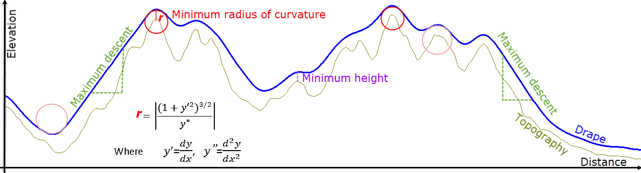
Minimum height
|
After applying the smoothing filter to the drape path, the elevation may drop lower the nominal height in some stretches. The minimum height defines the absolute lowest permissible height.
Script Parameter: QC_DRAPED_ALTITUDE. MIN_DRAPE_HEIGHT
|
|
Maximum elevation
|
Maximum elevation should not exceed this hard boundary. This value is in terms of absolute height and on the same datum as the DEM, rather than terrain clearance.
Script Parameter: QC_DRAPED_ALTITUDE. MAX_ELEVATION
|
|
Smooth drape
|
If checked, a pass of hanning filter is applied to smooth the draped surface.
Script Parameter: QC_DRAPED_ALTITUDE. SMOOTH[1- apply smoothing (default), 0- do not smooth]
|
|
Output drape channel
|
The draped vertical position for each X&Y coordinate in the input survey database is saved in the altitude channel.
Script Parameter: QC_DRAPED_ALTITUDE.ALTITUDE_CHANNEL
|
|
Set drape as current Z channel
|
If checked, the newly created drape channel is tagged as the Z coordinate.
Script Parameter: QC_DRAPED_ALTITUDE.SET_CURRENT_Z [1 -assign as Z coordinate (default), 0 - do not assign Z coordinate]
|
Disclaimer
This program is not to be used for the creation of the pilot's navigation flight plan for the execution of an airborne survey. The program creates an approximation of a draped flight path only for the purposes of investigating the efficacy of locating potential geophysical targets.
Application Notes
The draped surface is calculated along the survey line, using:
-
the Topography (DEM) as the base reference.
-
the gradient of ascent/descent to control the maximum slope along the flanks of a topography rise.
-
a minimum radius of curvature of 1000m to control the sharpness of the peaks and valleys.
*The GX tool will search in the "...\Geosoft\Desktop Applications \gx" folder. The GX.Net tools, however, are embedded in the geogxnet.dll located in the "...\Geosoft\Desktop Applications \bin" folder. If running this GX interactively, bypassing the menu, first change the folder to point to the "bin" folder, then supply the GX.Net tool in the specified format.
