
Create Isosurfaces from a Geosoft Voxel
A 3D surface that passes through points of equal value is called an isosurface. Isosurfaces can be thought of as 3D contours and can be used to visualize grade shells, or other volumes of interest. Isosurfaces are saved to a Geosoft geosurface file. The geosurface file can contain more than one isosurface. This enables you to easily share your results with colleagues to collaborate on projects.
In Oasis montaj, there are three different ways to create isosurfaces from a voxel:
-
Create a single isosurface at a specified value.
-
Visually clip the minimum data values from a voxel and automatically extract an isosurface at the specified clip value.
-
Automatically create multiple isosurfaces using a linear, log or user-specified distribution.
Create a Single Isosurface at a Specified Value
-
Select the Geosurface > New > Create Isosurface from Voxel menu option; in the 3D Viewer, select Geosurface > Isosurface > Create Isosurface.
The Create Isosurface from Voxel dialog appears. -
Using the Browse button, select the Input voxel.
-
You can optionally change the default Output geosurface name.
If the Output geosurface file exists, you can append the isosurface to it by selecting Append to geosurface.
-
In the Surface Properties section, specify the Value.
This will be the 3D contour value.
The value you enter must be a data value in the voxel range.
-
Click inside the Colour scheme to change the colour of your isosurface.
-
You can optionally choose to Create closed surface. Leaving this option unselected will create an Open isosurface.
-
Click OK to create the isosurface.
Visually Clip a Voxel to Create an Isosurface
-
Ensure you have a voxel displayed in the 3D Viewer (Add to 3D | Voxel).
-
Select the Voxel VOX_* in the 3D Viewer tree list.
-
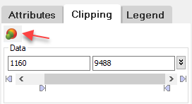
Select the Clipping tab below the tree list.
-
In the Minimum data value field, specify a value larger than the minimum and/or in the Maximum data value field, specify a value smaller than the maximum. You can type in a value or use the data slider.
-
Click the Define isosurface using data clipping values button (see below).
-
The Create Isosurface from Voxel dialog will open automatically populated with the Input voxel, Output geosurface name, Surface value(s) and Colour.
-
You can optionally choose to create closed isosurface. Leaving this option unselected will create an Open isosurface.
-
Click OK to create the isosurface.
-
You can optionally specify a different data value or range on the Clipping tab. Then use the Define isosurface using data clipping value again to append another isosurface to the geosurface file.
In the Create Isosurface from Voxel dialog:
-
isosurfaces can be appended to a geosurface as long as the input voxel used to create the geosurface is the same.
-
appending the same surface value to the geosurface will overwrite the surface value and will update the colour if it was changed.
-
if Append to geosurface is disabled and the output geosurface exists, you will be prompted to overwrite (or not) the output file.
Create Multiple Isosurfaces from a Voxel
-
Select the Geosurface > New > Create Multiple Isosurfaces from Voxel menu option; in the 3D Viewer, select Geosurface > Isosurface > Create Multiple Isosurfaces.
The Create Multiple Isosurfaces from Voxel dialog appears. -
Using the browse button, select the Input voxel.
If the options under Surface Properties are not changed, five open isosurfaces will be extracted at linearly-spaced intervals between the input voxel's minimum and maximum values.
-
You can optionally choose to Close the isosurfaces between value ranges. Leaving this option unselected will create a set of Open isosurfaces.
-
You can optionally change the Number of isosurfaces to extract (between 1 & 12).
-
You can choose to use a linear distribution (default) or to use a log distribution. You can then optionally change the Minimum and Maximum values used to define the range from which to calculate the isosurface values
-
You can manually change the Isosurface Value and Colour by clicking any cell in the table to edit.
-
Colour tables can be loaded and saved.
-
Click OK.
See Also:
Got a question? Visit the Seequent forums or Seequent support
© 2023 Seequent, The Bentley Subsurface Company
Privacy | Terms of Use