Georeference Section Image(s)
Use the Section Tools > Georeference Section Image(s) menu option (geogxnet.dll(Geosoft.GX.SectionTools.GeoreferenceSection;Run)*), to georeference an image.
Georeference Section Image(s) dialog options
|
Image
|
Select the image to georeference. This image would typically be a scanned or imported image of a section in any of the supported image formats.
Script Parameter: GEOREFERENCE_SECTION.INPUT
|
|
Reference plan map
|
This optional plan map must be in the coordinates into which the above image is projected. The map must cover the trace of the image. If provided, the georeferenced coordinates of the image can be obtained by clicking their corresponding locations on this map.
Script Parameter: GEOREFERENCE_SECTION.PLANMAP
|
|
Coordinate system
|
If the map specified above has a coordinate system, it will be displayed here. Otherwise click Define to provide the appropriate coordinate system
Script Parameter: GEOREFERENCE_SECTION.CS
|
|
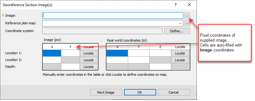
Locate
(inside the Image table)
|
When you select an image, its top left pixel coordinates populate the leftmost table of the dialog respectively in row Location 1. This is shown on the image with a black square. The default depth is populated with the pixel coordinate of the bottom of the image. However, you are not limited to the extreme points and can select other points along the top and bottom of the section.
You can proceed in two ways:
-
Click on the Locate buttons in this table to shift the focus to the image. Capture the coordinates of the intended point by left-clicking on the image. The corresponding cells in the Image table will be populated accordingly, OR
-
Manually edit the corresponding cells.
-
For a better accuracy, before clicking the left mouse button, you can pan and zoom the map using the right mouse button menu.
|
|
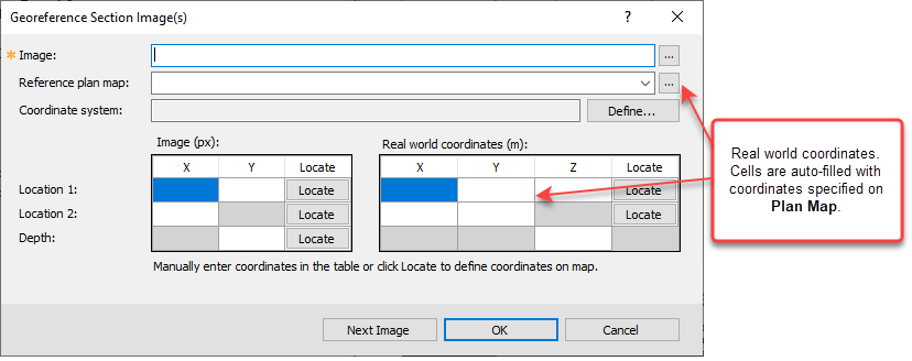
Locate
(inside the Real world coordinates table)
|
You can define the equivalent georeferenced coordinates on a reference plan map.
You can proceed in two ways:
-
Click on the Locate buttons in this table to shift the focus to the reference plan map. Capture the georeferenced coordinates of the corresponding point with a left-click. The cells in the projected table will be populated accordingly, OR
-
Manually edit the corresponding cells.
-
For a better accuracy, before clicking the left mouse button, you can pan and zoom the map using the right mouse button menu.
|
|
[Next Image]
|
You can define multiple section images to be georeferenced within the same invocation of this tool. Clicking on Next image saves the parameters for the current images, then clears the entries for entering the details of the next image. |
Application Notes
*The GX.NET tools are embedded in the geogxnet.dll file located in the "...\Geosoft\Desktop Applications \bin" folder. If running this GX interactively, bypassing the menu, first change the folder to point to the "bin" directory, then supply the GX.NET tool in the specified format. See the topic for more details on running a GX.NET interactively.
Old and historic data, and exported sections from some other software packages often are not georeferenced. 3D georeferencing of such section images allows recasting them in Oasis montaj as geophysical/geological sections. Once georeferenced, the image can be displayed on a georeferenced 2D section or a georeferenced 3D view, alongside other objects.
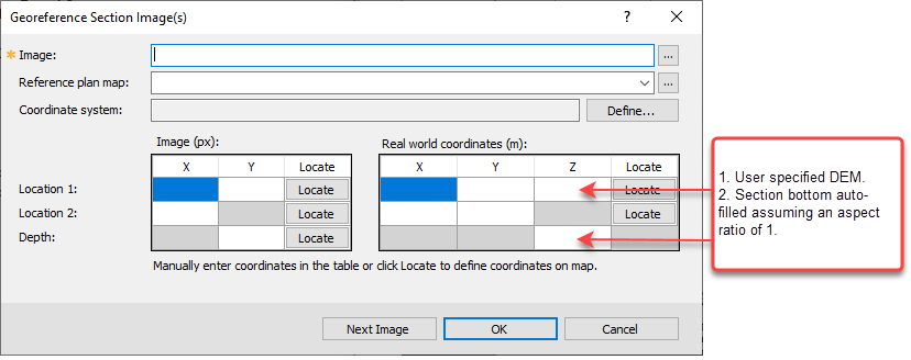
Using this tool, you can define two points along the top of an image and provide their georeferenced coordinates. You will manually enter the elevation datum of the image in the georeferenced coordinate system. This is a mandatory entry. If the image has a vertical exaggeration, you can rectify it by defining the bottom elevation as well.
The cells of both tables are editable. Although you can click on both the image and the plan map to obtain point coordinates and populate the corresponding cells, you can also enter the coordinates individually using the keyboard.
This tool allows for referencing of straight vertical sections only.