
Tilt Derivative
Use the Tilt Derivative option (TILTDRV GX) to calculate the tilt derivative of a grid and, optionally, the total horizontal derivative of the tilt derivative grid.
 Expand to view where this option is available:
Tilt Derivative dialog options
Application Notes
The tilt derivative and its total horizontal derivative are useful for mapping shallow basement structures and mineral exploration targets.
The tilt derivative is defined as:

Where VDR and THDR are first vertical and total horizontal derivatives, respectively, of the total magnetic intensity (T).
range


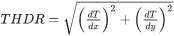
The total horizontal derivative of the tilt derivative is defined as:

Where HD_TDR is in units of radians/distance.
Tilt Depth Estimate
The tilt depth estimate is based on the technique published by Salem et al. (2008)[3]. This method is simple and fast for locating vertical contacts from Reduced-to-the-Pole (RTP) magnetic data. It relies on mapping specific contours of magnetic tilt angles:
-
Zero contours delineate the spatial location of magnetic source edges.
-
Depth to source is the distance between the zero contour and either the -45° or +45° contour, or their average.
The method assumes:
-
Source structures have vertical contacts.
-
There is no remanent magnetization.
-
Magnetization is vertical.
Tilt depth is calculated only at inflection points (zero values) in the tilt derivative grid, using the following expression:

The calculated depth is relative to survey elevation and uses the same units as the projected coordinate system of the input magnetic grid.
Advantages
-
Simplicity: Easy theoretical derivation and practical application.
-
Provides both qualitative and quantitative interpretation.
-
Allows visual inspection of tilt-depth maps to identify reliable depth estimates (these reliable locations can then be re-evaluated using other magnetic depth estimation methods) and areas affected by interference from magnetic anomalies.
-
Noise resistance: Uses first-order derivatives, making it less sensitive to noise compared to higher-order derivative methods.
-
Unlike Euler deconvolution, no need to choose window size or deal with clustered solutions.
References
- [1] H.G. Miller and V.J. Singh, "Potential Field Tilt - a New Concept for Location of Potential Field Sources", Journal of Applied Geophysics, vol. 32 (1994), no. 2-3, pp. 213-217.
- [2] B. Verduzco et al., "New Insights into Magnetic Derivatives for Structural Mapping", The Leading Edge, vol. 23 (2004), pp. 116-119.
- [3] A. Salem, S. Williams, J. D. Fairhead, R. Smith, and D. Ravat, "Interpretation of magnetic data using tilt-angle derivatives", Geophysics, vol. 73 (2008), no. 1, pp. L1-L10.
Got a question? Visit the Seequent forums or Seequent support
Copyright (c) 2026 Bentley Systems, Incorporated. All rights reserved.
Privacy | Terms of Use