
Advanced Settings
Use the Project > Settings > Advanced (ADVSETTINGS GX) option to modify the global advanced settings for your Oasis montaj environment.
These settings are installation-specific, meaning they apply to all projects on the same computer. They control default behaviours in Oasis montaj, Target, and any licensed extensions.
When the application starts, it loads the contents of the advanced settings file—geosettings.meta—located at:
%USERPROFILE%\Documents\Geosoft\Desktop Applications\ini.
The values in this file are applied as default settings throughout the application.
Advanced Settings dialog options
The dialog is organized into two main sections:
-
A list of available application settings.
-
A table displaying the attributes and corresponding values for the selected setting. You can modify values as needed.
Refer to the Application Notes for examples of commonly used settings.
For frequently used global settings, use the General Settings dialog, available from Project > Settings > General. The Advanced Settings dialog provides access to the complete set of configuration options.
|
Application Settings |
When you select an item in the Application Settings tree, its associated attributes and values appear in the table.
|
||||
|
|
|||||
Attribute Icons
The icon to the left of each attribute (a white letter in a grey circle) indicates the attribute’s data type.
|
|
A whole number (positive, negative, or zero) within the range –32,768 to 32,767. |
|
|
A whole number that can only be zero or positive. |
|
|
A number with both integer and fractional parts. Represented using the primitive type double or float. |
|
|
A sequence of characters, also referred to as text or a text string. |
|
|
A reference to an object such as a boundary polygon, META object, or projection object. Typically, this is an item that can be activated by double‑clicking the cell. The action performed depends on the context and the object currently displayed. |
|
|
A predefined list of named values that define the allowable range for a particular attribute type, typically displayed in a dropdown list. |
 Integer
 Unsigned Integer
 Real Number
 String
 Object
 Enum
EnumApplication Notes
Below are examples of advanced settings parameters that can be viewed or modified in the Advanced Settings dialog.
Key points:
-
Values shown in grey fields are read-only.
-
Values shown in white fields are editable.
-
Some changes made while Oasis montaj is running may not take effect until the next application session.
-
All values are stored in the geosettings.meta file located at: %USERPROFILE%\Documents\Geosoft\Desktop Applications\ini.
-
You can copy this file to another computer to transfer your advanced settings configuration.
Auto Save Time
The Auto Save Time setting triggers a reminder after a specified time interval, prompting you to save any open documents.
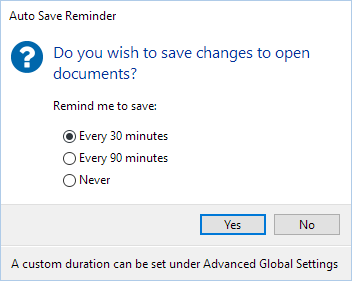
When you click Yes in the Auto Save Reminder dialog, all currently open documents—such as databases, grids, maps, geosurfaces, 3D views, VOXI projects, and GMSYS projects—are saved automatically.
The dialog provides three default reminder intervals:
-
Every 30 minutes
-
Every 90 minutes
-
Never
To set a custom reminder interval:
-
Select the top-level Application Settings entry to display its full list of attributes.
-
In the Attribute column, locate Auto Save Time
-
Enter your desired reminder interval (in minutes).
To disable auto‑save reminders, set the Auto Save Time value to 0 (zero).
-
Restart the application for the change to take effect.
Set Default Project Directory
Setting a consistent location for your projects helps keep files organized and ensures smoother integration with cloud‑based workflows.
By default, your projects are stored in your user profile’s Documents folder:
%USERPROFILE%\Documents\Geosoft Projects
The Geosoft Projects folder is created automatically if it does not already exist.
To change the default project directory:
-
Select the top-levelApplication Settingsentry to display all attributes and values.
-
Find Default Project Directory in the attributes list.
-
Enter the new directory location, and click OK to save the change.
All new projects will now be created in the directory you specified.
Default Settings for Databases
You can change the default alignment of channel names when opening databases from the Project Explorer. By default, channel names are centre-aligned.
To modify channel name alignment:
-
Open the Database Settings node. In the Attribute / Value table, scroll to Channel Name Alignment.
-
To left-align channel names, set the value to Left. The layout adjusts automatically to accommodate any protected channels.
-
To right-align channel names, set the value to Right. This layout adapts to display the x/y /z marker, if present.
Changes apply immediately to all databases—both open and closed—within the current project. You do not need to save or reopen the project.
Default Settings for Grids and Images
Enabling Colour‑shaded Grid Display
You can configure Oasis montaj to automatically display grids as colour-shaded grids when they are opened from the Project Explorer.
To enable colour‑shaded grid display:
-
In the Application Settings tree, select Image Settings to display its attributes.
-
Locate the Colour-shaded Grids attribute (its default value is False).
-
Change the value to True, then click OK.
Any grid opened from the Project Explorer will now display as a colour‑shaded grid in the grid viewer.
Adjustments to shadow inclination, declination, and scale made inside the grid viewer are not preserved when the view is reopened from the Project Explorer. To retain the changes, save the grid view to a new map.
Setting Default File Types for Grids and Images
You can specify default grid or image file types (file decorations) used in dialogs or GXs when browsing for files. These defaults are set through the Advanced Settings dialog. If you frequently use certain raster or image formats, you may want to set them as your new default.
Example: Set ER Mapper as the default grid format
-
In the Application Settings tree, select Image Settings.
-
In the Attribute / Value table, locate Default XGD IN Format.
-
Enter the full name of the desired default file format.
For ER Mapper files, enter: ERS Mapper data (*.ers)
-
Restart Oasis montaj.
Now, when browsing for a grid file, the file type will default to the ER Mapper ERS format.
Default Settings for Maps
Pinning the Map Manager
You can specify whether the Map Manager opens in a pinned or unpinned state when creating or opening a map from the Project Explorer.
To set the Map Manager pinning option:
-
Select the Map Settings node.
-
In the Attribute column, locate the Pin Map Manager entry.
-
Set the value to one of the following:
-
True – The Map Manager opens pinned. When you open or create a map, the Map Manager appears automatically and the map resizes to make room for it.
-
False – The Map Manager opens unpinned. It appears as a tab on the left side of the map, and the map resizes accordingly.
Mouse Wheel Zoom Behaviour
You can customise how the mouse wheel controls zooming within map and grid windows* using the settings described below.
To change the mouse wheel zoom mode:
-
Select the Map Settings node.
-
In the Attribute column, locate Mouse Wheel Zoom Mode.
-
Select one of the following options:
-
Cursor Position (default)
Zooming is centred on the current cursor location. When you roll the mouse wheel, the view zooms in or out around the point directly beneath the pointer.
-
Map Center
Zooming is centred on the centre of the window. Scrolling the mouse wheel zooms the view in or out around the window centre, regardless of the cursor position.
To change the mouse wheel zoom direction:
-
Select the Map Settings node.
-
In the Attribute column, locate Mouse Wheel Zoom Direction.
-
Select one of the following options:
-
Scroll Up to Zoom Out (default)
-
Rolling the mouse wheel forward (away from you) zooms out.
-
Rolling the mouse wheel backward (toward you) zooms in.
-
-
Scroll Up to Zoom In
-
Rolling the mouse wheel forward (away from you) zooms in.
-
Rolling the mouse wheel backward (toward you) zooms out.
-
*These settings apply to map and grid viewers, map template editors, and print preview windows.
OpenGL Settings
OpenGL (Open Graphics Library) is an industry-standard, cross-language, cross-platform application programming interface (API) used for rendering 2D and 3D vector graphics. OpenGL drivers are typically installed along with your graphics driver and related support software. NVIDIA provides full OpenGL support—visit the
By default, Geosoft Desktop Applications use OpenGL 3.3 or higher to render high-quality 3D graphics. Most modern video cards support OpenGL 3.3; however, older hardware or outdated/unstable drivers may cause 3D rendering performance issues.
If you suspect a graphics‑related issue, consider the following steps:
- Update Your Graphics Drivers
Your first step should be to ensure your graphics drivers are up to date:
- Open Device Manager from the Control Panel.
- Under Display adapters, right-click your graphics card and select Update driver.
- Install any available updates, then restart your computer.
- Ensure Oasis montaj Uses the Discrete GPU
If your system has multiple GPUs, make sure Oasis montaj is using the discrete GPU rather than the integrated graphics adapter (e.g., Intel UHD Graphics), which offers lower performance. This is especially important for large or graphics‑intensive 3D projects.
Most computers and laptops include:
-
Integrated graphics (e.g., Intel UHD Graphics): lower performance, lower power usage
-
Dedicated graphics (NVIDIA or AMD): higher performance, higher power usage
 Expand to read more about the difference between integrated graphics and discrete graphics
Configuring Oasis montaj to use the discrete GPU:
- Open the Advanced Settings dialog.
- Navigate to Application Settings -> OpenGL Settings.
- In the Attribute / Value table, ensure Use Discrete GPU is set to True.
To manually configure Windows to use a high‑performance GPU with Oasis montaj, follow the steps in one of these articles:
If your system has separate output ports for integrated and discrete graphics cards, ensure your external monitor is connected to the correct output—especially when using a docking station.
-
- Enable Software Rendering (Temporary Solution)
If the issue persists—or if your system lacks a dedicated graphics card and its integrated graphics are insufficient—you can enable Oasis montaj’s software rendering mode. This forces 3D rendering to be performed by the CPU instead of the graphics card.
To enable software rendering:
- Open the Advanced Settings dialog.
- Under Application Settings, select OpenGL Settings.
- In the Attribute / Value table, the default values are:
Use Software Rendering: False
Use Discrete GPU: True
- Change Use Software Rendering to True to enable software‑based rendering (instead of relying on the graphics card).
- Set Use Discrete GPU to False to disable the discrete graphics card. This will trigger a prompt to restart Oasis montaj.
Software rendering can be significantly slower and should be used only as a temporary workaround. For best performance, ensure your graphics drivers are up to date and Use Discrete GPU remains set to True. Refer to the
See Also:
Got a question? Visit the Seequent forums or Seequent support
Copyright (c) 2026 Bentley Systems, Incorporated. All rights reserved.
Privacy | Terms of Use