The Modify tab of the Section Tool can be used to modify existing cross sections, by editing the section location parameters, or by re-drawing them on the active scene or map.
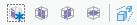
At the top of the Modify tab there is a tool strip with 5 buttons:
Modify section by drawing on current map or view - press this button in order to re-define the location of a section, by drawing on the active map or scene.
Constrain drawing as an East-West section - press this button to force the section to be drawn only in the East-West orientation. Press again to remove this constraint.
Constrain drawing as a North-South section - press this button to force the section to be drawn only in the North-South orientation. Press again to remove this constraint.
Constrain drawing as a Plan (horizontal) section - press this button to force the section to be drawn only in the Plan (horizontal) orientation. Press again to remove this constraint.
Change Drawing Mode to Parallel/Perspective - press this button to switch the drawing mode. Parallel mode is easier to use when drawing section locations.
From the top-most Section drop down list, select the section you want to modify. The section location parameters appear in the tool and a red outline box appears in the scene to show the section location.
Once you have clicked Modify section... ( ), the scene will rotate to a top-down (bird's eye) view, so that you can draw the sections extents by following these steps:
Pressing the Save button after the section location parameters are correctly set, will commit the current section location to the drillhole dataset. You may also Cancel the modifications and revert back to the original section parameters, or Delete the section from the dataset.
| Parameter | Explanation |
|---|---|
|
Section |
|
|
Section |
Select the section to be modified from the drop down list of all sections in the dataset. |
|
Name |
The name of the section. This will be automatically filled in based on the location. |
|
Create Offset Sections |
Slide the toggle on to create multiple, offset parallel sections. In the Modify tab, this can be used to create multiple sections that are parallel to the selected section. |
|
Count |
The number of offset sections to create, in addition to the original base section. |
|
Separation |
The separation spacing between offset sections. Enter a negative value to force the sections to be created in the opposite direction. |
|
Reference Point: the reference point is located at the top-center of the section |
|
|
Easting (X) |
The X or easting location of the section reference point. |
|
Northing (Y) |
The Y or northing location of the section reference point. |
|
Elevation (Z) |
The Z or elevation location of the section reference point. |
|
Offset |
|
|
Offset toggle |
Move section perpendicular to Azimuth. When working with angled sections, adjusting the easting or northing location of the reference point can lead to accidentally moving the section away from the desired location. This option allows you to hold the reference point and azimuth constant, while moving the section in a direction perpendicular to the azimuth. Enabled by default, slide toggle to off position in order to adjust Easting or Northing locations independently. |
|
Distance |
Moves the section location by this distance, perpendicularly, from the original section location. |
|
Angles |
|
|
Azimuth |
The angle of the section plane, measured clockwise from North (0°) degrees. |
|
Inclination |
The angle of the section plane, measured from horizontal (0°) degrees. |
|
Extents |
|
|
Length |
The length of the section; changes to the length will expand the section outward in both directions from the center reference point. |
|
Height |
The height of the section; changes to the height will move the bottom of the section only. The top location is fixed by the reference point Z value. |
|
Thickness |
The thickness of the section; in the direction perpendicular to the length. Changes to the thickness will expand the section outward in both directions from the center reference point. |
|
Scenes |
|
|
Show extents as box |
Slide on or off to view the sections extents in the current scene. Section extents appear as a red outline box. |
|
Clip to extents |
Slide on or off to temporarily clip the extents of the current scene to the extents of the section. |
|
Clip to center plane |
Slide on or off to temporarily clip the extents of the current scene to the center plane of the section. |
When drawing section locations, it is much easier to achieve a precise location when in Parallel Drawing mode. If the scene is using Perspective Drawing mode, a warning will appear in a yellow text beneath the toolbar advising the user that sections might not be located as expected when using Perspective mode. Switching to Parallel mode will remove this warning, and provide a better experience when defining sections. The Drawing Mode selector is available on the View ribbon, in the Scene group. There is also a shortcut to this same control on the Create and Modify Section tabs.
|
Access MyGeosoft Support >> for online support and learning resources: Knowledge Base Articles, Guided Learning Path Lessons, Instructional Videos, Technical and Technology Papers, and Best Practices. |
|