
Gradient Sensor Offset Correction
Use the Gradient Sensor Offset Correction option (Geosoft.uxo.gxnet.dll(Geosoft.GX.UXO.UxoOffsetCorrection;Run)*) from the UXO-Marine Grad > Path Corrections menu to determine the position for each sensor in a gradient or multi-sensor array database.
Calculate Correct Offset Position for each Sensor dialog options
X (Easting) channel | Select the X (Easting) channel. Script Parameter: UXOOFFSETMULT.X_CHANNEL |
Y (Northing) channel | Select the Y (Northing) channel. Script Parameter: UXOOFFSETMULT.Y_CHANNEL |
Z (Altitude) channel | Select the Z (Altitude) channel. Script Parameter: UXOOFFSETMULT.Z_CHANNEL |
Depth channel | Select the depth channel. Script Parameter: UXOOFFSETMULT.DEPTH_CHANNEL |
Label position | Select the label position, which determines how the output channels will be named. Default value is Suffix. Script Parameter: UXOOFFSETMULT.LABEL_POSITION |
Longitudinal axis rotation (roll) channel | Select the longitudinal axis rotation (or roll) channel. Script Parameter: UXOOFFSETMULT.ROLL_CHANNEL |
Transverse axis rotation (pitch) channel | Select the transverse axis rotation (or pitch) channel. Script Parameter: UXOOFFSETMULT.PITCH_CHANNEL |
Vertical axis rotation channel | Select the vertical axis rotation channel. Then, select whether the vertical axis rotation channel selected above, is a Yaw or a Heading channel. Script Parameter: UXOOFFSETMULT.YAW_CHANNEL |
Number of sensors | Select the number of sensors in the gradient array, which cannot be less than 2. Default value is 2. Script Parameter: UXOOFFSETMULT.NO_OF_SENSORS |
Sensor Configuration TableThe sensor configuration table contains the label and offset data for all the sensors. Script Parameter: UXOOFFSETMULT.SENSOR_TABLE | |
Sensor label | Specify the sensor label. The name of the output channels are formed based on the label and Label position, for example, when the label is a prefix, the channel name will be, "label_channelname" and when the label is a suffix, the channel will be, "channelname_label". |
Along track (X) offset (m) | Specify the along track (X) offset in, in metres. |
Horiz. across track (Y) offset (m) | Specify the horizontal across track (Y) offset in, in metres. |
Vertical across track (Z) offset (m) | Specify the vertical across track (Z) offset in, in metres. |
[Load Table] | Select the Load Table button to load the Sensor Configuration table from a CSV file. See the Application Notes below for information on the sensor configuration CSV file format. |
[Save Table] | Select the Save Table button to save the Sensor Configuration table to a CSV file. See the Application Notes below for information on the sensor configuration CSV file format. |
More | |
Sampling threshold | Specify the sampling threshold, in distance units. The default is 1/5 of the average distance interval of the first 10 non-zero points. Click the Calculate button to re-calculate the default value. Script Parameter: UXOOFFSETMULT.THRESHOLD |
Smoothing interval for course over ground (COG) | Specify the smoothing interval, in distance units. The default is 5. Script Parameter: UXOOFFSETMULT.SMOOTH |
Application Notes
When the Calculate Correct Offset Position for each Sensor dialog is executed, the following 4 channels will be created for each sensor in the Sensor configuration table: X, Y, Z , and Depth. For instance, if the sensor label is Port, and the label position is Suffix, the output channels will be: X_Port, Y_Port, Z_Port, and Depth_Port.
On a survey frame, the sensors are located at a fixed geometry relative to each other and the tow / measurement point. Knowing the direction of motion along the survey path, and the sensors fixed geometry, the absolute position of each sensor can be deduced. The offset should be provided in a Cartesian right-handed system. This geometry is then used to calculate the absolute location of each sensor.
The algorithm to determine a sensors location is as follows:
- Determine average distance between points by averaging the first ten non-zero distances. The default threshold is one fifth of this average distance. The distance units are those from the coordinate channels.
- Smooth the path over the specified smoothing interval.
- Thin input points to be at least the smoothing interval apart.
- Re-interpolate the thinned points at the original average distance.
- For each input point, using the smoothed curve, calculate the bearing from the adjacent points.
- Apply the offset for each sensor.
After the processing, a GradientSensorOffsetCorrection_Summary.txt file is created for the summary that all line/sensors have been processed or skipped based on lack of data.
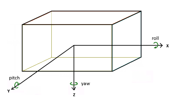
Roll/Pitch/Yaw
The more recent survey systems record the Roll/Pitch/Yaw of the sensor frame. The illustration below shows the direction and positive sense of these three components. Note that, Yaw depicts the heading of the survey.
Sensor Configuration Table File Format (CSV)
The Sensor Configuration Table file format (*.CSV) must include 4 columns, Sensor Label, Along Track (X) Offset (m), Horizontal Across Track (Y) Offset (m), and the Vertical Across Track (Z) Offset (m), as shown in the CSV Table file example below:
Port 0 -0.75 0 Starboard 0 0.75 0 Vertical 0 0 -0.5 Aft -1.1 0 0
The Sensor Configuration Table file (*.CSV) can be edited in any text editor.
*The GX tool will search in the "gx" folder. The GX.Net tools, however, are embedded in the Geosoft.uxo.gxnet.dll located in the bin folder. If running this GX interactively, bypassing the menu, first change the folder to point to the bin folder, then supply the GX.Net tool in the specified format.
Got a question? Visit the Seequent forums or Seequent support
© 2024 Seequent, The Bentley Subsurface Company
Privacy | Terms of Use