
Azimuth Test
Use the Azimuth Test option (UCEAZIMUTH GX) to calculate and display results from an "Azimuth Test" (see also UCEOCTANT GX).
Azimuth Test dialog options
Azimuth database | Please enter the name of the Geosoft database that contains the azimuth test data. If a database is already open and selected in the current Oasis montaj project window, it will be displayed as the default database. Script Parameter: UCEAZIMUTH.GDB |
Azimuth channel | The azimuth channel is the directional channel and should be in degrees. This channel is generated by the user prior to running this test. Script Parameter: UCEAZIMUTH. AZIM |
Data channel | The data channel to be used for the test. Script Parameter: UCEAZIMUTH. CHAN |
Amplitude tolerance | The Amplitude tolerance in instrument units. All amplitudes beyond the mean +/- the tolerance are flagged with a red triangle on the map. Script Parameter: UCEAZIMUTH. DY |
Sensor head angle | The angle of the sensor head with the vertical. Script Parameter:UCEAZIMUTH. HEADING |
Update List | When entering a new database name, in order to refresh the list of the channels, please click this button. |
OK | Proceeds with generating the map. |
Application Notes
An "Azimuthal Test" can be performed to document the differences in readings based on the sensor’s orientations. It is recommended that this test be performed for all proposed magnetometer configurations. A pictorial illustration of the "Azimuthal Test" is seen in Figure 1.
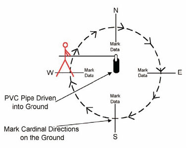
Figure 1. Pictorial representation of the Azimuthal Test.
Conducting an "Azimuthal Test"
- Identify an area free of cultural sources of geophysical noise. When this test is performed near a magnetic gradient, small shifts in the sensor head position will produce large variations in the total field values.
- The sensor must be maintained in a fixed position while the operator revolves slowly around it. Placing the sensor head through a hole in the top of a non-magnetic table or into the top of a vertical section of PVC pipe will help to stabilize it.
- Mark the four cardinal directions on the ground using pin flags or marking paint. Recording fiducial marks at the moment the operator is facing cardinal directions will aid in determining the heading error for particular survey line directions.
- Using a fully warmed-up instrument, begin data collection while facing north, and slowly move in a clockwise circle, pivoting around the table or PVC pipe. Place a marker (fiducial) in the data when reaching each of the cardinal directions. These markers will be used to plot the direction the operator was facing as data points were collected.
- Different orientations may need to be evaluated to minimize any observed deviation in amplitude or any magnetic "dead zones" that are encountered.
This GX will help to provide heading correction information. It reads the azimuthal information from the database and requires the user to specify the azimuth and reference channels, as well as an amplitude tolerance (as a percentage).
The GX produces a figure showing the heading in all directions and will flag directions in which the amplitude tolerance was exceeded.
Acknowledgments
The following document has been used in the compilation of this Help file, and further information can be obtained directly from it:
- ORDNANCE AND EXPLOSIVES DIGITAL GEOPHYSICAL MAPPING GUIDANCE - OPERATIONAL PROCEDURES AND QUALITY CONTROL MANUAL (DGM QC Guidance), U.S. Army Corps Engineering and Support Center, Huntsville, Prepared by NAEVA Geophysics, Inc. December 2003.
Got a question? Visit the Seequent forums or Seequent support
© 2024 Seequent, The Bentley Subsurface Company
Privacy | Terms of Use