
Sensor Offset Corrections
Use the Sensor Offset Corrections option (UCEOFFSETMULT GX) to calculate the true X, Y coordinates for up to 10 sensors which are located at fixed offsets from the GPS receiver. Up to 10 channels can be associated with each sensor and copied to the new line version in the new database that is created for each new set of sensor coordinates.
Sensor Offset Corrections dialog options
Input database name | The name of the input database. Script Parameter: UCEOFFSETMULT.GDB |
Number of sensors in array | Specify the Number of sensors in the towed array which are offset from the GPS receiver location. We currently support up to 10 different sensor offsets. Script Parameter: UCEOFFSETMULT.NUMSENS |
Number of database channels per sensor | Specify the Number of channels associated with each offset sensor. The maximum number of channels per sensor is 10. Script Parameter: UCEOFFSETMULT.NUMCHANS |
Lines to correct | Select which line(s) to process. Script Parameter: UCEOFFSETMULT.LINES |
Roll channel | Select the Roll channel if the roll angle has been recorded, if not leave this entry blank. Script Parameter: UCEOFFSETMULT.ROLL |
Pitch channel | Select the Pitch channel if the pitch angles have been recorded, if not leave this entry blank. Script Parameter: UCEOFFSETMULT.PITCH |
Yaw channel | Select the Yaw channel if the yaw angles have been recorded, if not leave this entry blank. Note that this is actually the heading of the sensor cart. Script Parameter: UCEOFFSETMULT.YAW: UCEOFFSETMULT.YAW |
X backup channel | Select the default X backup channel name, or specify a new X backup channel name. The original X channel will be saved under this channel name. Script Parameter: UCEOFFSETMULT.X |
Y backup channel | Select the default Y backup channel name, or specify a new Y backup channel name. The original Y channel will be saved under this channel name. Script Parameter: UCEOFFSETMULT.Y |
Other non-data channels | Select other non-data channels to save to output database, None or Select from a list. If you choose Select from a List, the Select other non-data channels dialog will be displayed. Using this dialog, select the other non-data channels that you want to include in your output database. Script Parameter: UCEOFFSETMULT.NONDATACHANS |
Output database name | Specify the name of the database to which the new coordinate, data channels and selected non-data channels will be written. Script Parameter: UCEOFFSETMULT.GDBOUT |
Prefix of combined channel | Specify the prefix string for the output combined channels. Default is "Combined". See the Application Notes below for more detailed information. Script Parameter: UCEOFFSETMULT.COMBINEDPREFIX |
[Next>] | To advance to the next dialog in the Apply position offset correction wizard. |
"One" Channel per Sensor dialog options
Sensor data channel | Select the data channel associated with sensor. Script Parameter: UCEOFFSETMULT.FIRST_CHAN1 |
Sensor offset in direction of travel | Specify the distance of the sensor ahead (positive) or behind (negative) to the GPS receiver, relative to the line direction. Script Parameter: UCEOFFSETMULT.OFFSETA1 |
Sensor offset across direction of travel | Specify the offset distance of the sensor perpendicular to line direction (positive to right relative to line direction). Script Parameter: UCEOFFSETMULT.OFFSETP1 |
Sensor vertical offset | Specify the vertical offset distance of the sensor above (positive) or below (negative) to the GPS receiver, relative to the line direction. |
Sampling Threshold | Specify the acceptance threshold, which must be > 0.0. Script Parameter: UCEOFFSETMULT.THRESHOLD |
Smoothing interval for heading | Specify the smoothing interval for the heading. Script Parameter: UCEOFFSETMULT.SMOOTH |
[Preview] | Click this button to preview the "Multi-sensor layout.map". |
Z Channel Offset dialog options
Z channel | Select the Z channel that is associated with sensor(s). Script Parameter: UCEOFFSETMULT.ZCHAN |
Elevation offset | Specify the distance of the sensor above the GPS receiver. Script Parameter: UCEOFFSETMULT.ELEVATION |
Application Notes
On a survey cart, the instruments are located at a fixed geometry relative to each-other and the GPS device. Knowing the direction of motion along the survey path, and the instrumentation fixed geometry, the absolute position of each sensor can be deduced.
The line name in the input database can only be an integer number; any letters in the line names are not supported.
The Sensor Offset Corrections option prompts the user for the offset of each sensor relative to the GPS device, and in the direction of motion. The offset should be provided in a Cartesian right-handed system. The offset can be specified in up to 3 dimensions. This geometry then is used to calculate the absolute location of each sensor. The user can provide offsets for up to 10 separate sensors. The path is smoothed prior to calculating the heading. The user has control over the level of smoothness applied. The offset is then applied to the smoothed path and in the direction of motion. Smoothing is necessary in order to overcome potential reversal of the course, which may simply be due to changes in the slope or operator stoppage along the path. The positive X-Axis is always along the direction of motion. For each sensor a new line is generated and saved to the database. These lines maintain the name of the original line and have incremental version numbers.
The algorithm is as follows:
- Determine average distance between points by averaging the first ten nonzero distances. Then the default threshold is calculated by one fifth of this average distance. The distance units are those from the coordinate channels.
- Smooth path over the interval specified by the user.
- Thin input points to be at least the smoothing interval apart from each other.
- Re-interpolate the thinned points at the original average distance.
- For each input point, calculate the bearing using the nearest points on the smoothed curve.
- Apply the offset.
Roll/Pitch/Yaw
The more recent survey systems record the Roll/Pitch/Yaw of the sensor cart. Given the sensitivity of the positioning of UXO surveys, it is recommended to apply the geometric correction in conjunction with the offset correction, in particular in uneven terrain, this correction is imperative. The illustration below shows the direction and positive sense of these three components. Note that, Yaw depicts the heading of the survey.
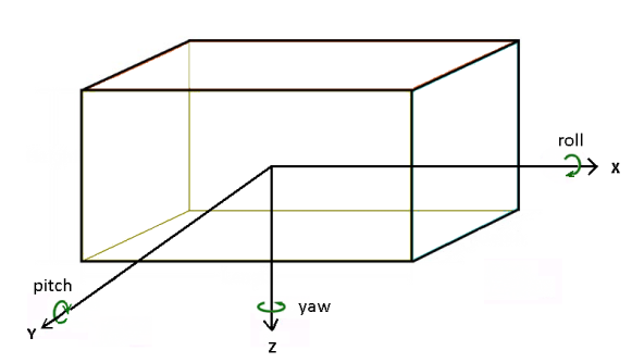
Figure 1: Axis and positive sense relative to the direction of travel
The supporting trigonometric transformation applied in conjunction with the offset correction is extracted from http://cimss.ssec.wisc.edu/seminars/CIMSS_Seminar_Feng_June06.pdf and formulated below:
dx = x_offset x cos(Pitch) x cos(Yaw)+y_offset x cos(Pitch) x sin( Yaw) - z_offset x sin(Pitch)
dy = x_offset x [ sin(Roll) x sin(Pitch) x cos(Yaw) - cos(Roll) x sin(Yaw)]+ y_offset x [sin(Roll) x sin(Pitch) x sin(Yaw) + cos(Roll) x cos(Yaw) ] - z_Offset x sin(Roll) x cos(Pitch)
dz = x_offset x [ cos(Roll) x sin(Pitch) x cos(Yaw) + sin(Roll) x sin(Yaw)]+ y_offset x [cos(Roll) x sin(Pitch) x sin(Yaw) - sin(Roll) x cos(Yaw) ] - z_Offset x cos(Roll) x cos(Pitch)
Combined Channel
Often it is desirable to combine the various sensor data of the same array in order to grid it together. The data of the different sensors is originally imported under different channel names. As a by-product this tool generates a "combined" channel that will contain the data of all the different sensors. In order to grid the combined data together we make the following assumptions:
- The sensors are all at the same elevation
- The sensors have been calibrated to the same base
Use with care the combined channel, as the software is unable to judge it the data will properly merge.
Array Channels
Array channels are now supported. However, note that when inputting an Array channel you must be consistent with the Array type and Array size. For example, if you select 6 channels per sensor and for sensor 1 you select Channels 1, 2 and 5 as Array channels and sensor 3,4, and 6 as non-Array channels, then for all sensors you must select Channels 1, 2 and 5 as Array channels and sensor 3, 4, and 6 as non-Array channels, the channels must be consistent for all sensors. An error message will be displayed if your channel types and sizes are not consistent.
Got a question? Visit the Seequent forums or Seequent support
© 2024 Seequent, The Bentley Subsurface Company
Privacy | Terms of Use