
Specify TDEM Waveform
Use the Specify TDEM Waveform dialog to define the waveform data for the inversion. This dialog is displayed whenever TDEM Waveform and Time Windows is instantiated and no waveform is currently defined for the active session or when the [Specify] button is pressed in the TDEM Waveform and Time Windows window.
Upon closing this dialog and returning to TDEM Waveform and Time Window – the waveform definition will be updated along with the graphical displays (the TDEM waveform and time windows).
Specify TDEM Waveform dialog options
|
Waveform |
Select From database if you specify the waveform from a database; select one of the two options, Ramp off or Step off, to explicitly define the waveform. |
|
From database: |
|
|
Waveform database |
This is a Geosoft database containing the time, transmitter current, and optionally, receiver voltage values of the waveform. You can select a different waveform database by clicking on the browse [...] button. |
|
Time channel |
Select the channel containing the times. The units for the channel must be defined.
|
|
Channel to upload |
Explicitly identify the nature of the waveform channel to use in the inversion process, as either the transmitter current (the Tx option) or the receiver voltage (the Rx option). |
|
Waveform channel |
Select the channel containing the waveform to upload. The units for the channel must be defined.
|
|
Ramp off: |
|
|
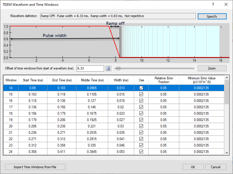
Pulse width |
Enter a value for this parameter or accept the default. The maximum pulse width is the system half period (entered in the system description); the minimum value is zero. The default value is 1/2 the half period (1/4 of the system period). |
|
Ramp width |
Enter a value for this parameter or accept the default. The maximum value of the ramp width is the pulse width; the minimum value is zero. The default value is 1/10 of the pulse width. |
|
Repetitive |
Check on/off this option to indicate if the waveform is repetitive. |
|
Step off: |
|
|
Pulse width |
Enter a value for this parameter or accept the default. The maximum pulse width is the system half period (entered in the system description); the minimum value is zero. The default value is 1/2 the half period (1/4 of the system period). |
|
Repetitive |
Check on/off this option to indicate if the waveform is repetitive. |
Application Notes
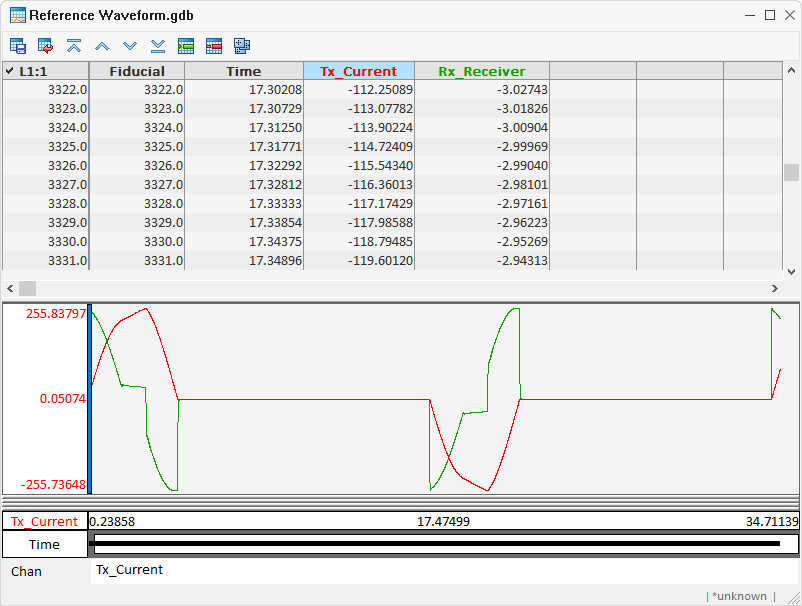
There is variability in the waveform from survey to survey and also from country to country. The waveform is generally supplied as a database along with the survey data. The waveform database contains the channels Fiducial (optional), Time, and either Tx current or Rx voltage. The units for the channels in the waveform and in the surveyed data must be specified. The onus is on you to ensure that the data units are properly assigned. Ideally, you should know if the data is in absolute or normalized units and provide the units accordingly.
The standard waveform database consists of the fields:
-
Fiducial: Unique fiducial number.
-
Time: The current is recorded at specific times relative to the start of a cycle. The tool searches for the term “time” imbedded in the channel name and if not found you will be informed that the time channel is missing.
One of the following two channels must be present.
-
Tx_Current: Current at transmitter at the designated times.
-
Rx_Receiver: Voltage at receiver, equivalent to dI/dt.
The waveform database contains as many lines as flights in the project. There is usually one waveform per survey flight, and the waveforms may vary somewhat from flight to flight. Generally, each cycle in the waveform consists of a positive and a negative pulse. VOXI requires a single pulse. As a result, the waveforms over all the flights are first averaged, then the cycle length is determined as the inverse of the frequency defined in the configuration file. If the cycle consists of two pulses, only half the cycle (first half of the waveform of all flights in the database is averaged) is sent to the inversion engine.
Waveform database example:
Example of pulse width and ramp off effect:
Got a question? Visit the Seequent forums or Seequent support
© 2024 Seequent, The Bentley Subsurface Company
Privacy | Terms of Use