
Design Models
This topic describes how to import and work with designs and alignments in Leapfrog Works. It is divided into:
Designs
Leapfrog Works imports designs in the following formats:
- DGN (*.dgn)
- DWG (*.dwg)
- DXF (*.dxf)
This includes Autodesk Civil 3D objects in *.dwg format.
For DGN files:
- Xrefs are not supported and the externally referenced data will need to be imported into Leapfrog Works separately.
- For files that contain ‘Complex Elements’, it may be necessary to first ‘Drop Elements’ in the Bentley design software before importing it into Leapfrog Works.
When you are importing Civil3D objects, note that some object types can be imported into Leapfrog Works directly, while others must be exploded before they can be imported.
| Object | Imported As | Notes |
|---|---|---|
| Alignments | Design line | |
| Corridors | Design mesh | |
| Feature lines | Design line | |
| Fittings | Design mesh | Needs to be exploded in Civil3D |
| Intersections | Design line | |
| Parcels | Design line | |
| Match lines | Design line | |
| Pipes | Design mesh | Needs to be exploded in Civil3D |
| Pressure pipes | Design mesh | Needs to be exploded in Civil3D |
| Sample lines | Design line | |
| Structures | Design mesh | Needs to be exploded in Civil3D |
| Surfaces | Design mesh | Needs to be exploded in Civil3D |
To import a design, right-click on the Designs folder and select Import Designs. In the window that appears, navigate to the folder where your design is stored and select the files you wish to import. You can use the Shift and Ctrl keys to select multiple files. Click Open.
All models and layers available in the selected files will be displayed. Here three files have been selected for import, FLYOVER_Tunnel, Tunnel and visualization_-_apt_block:
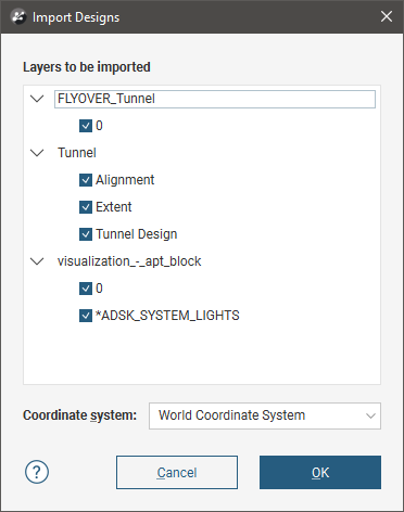
Select the layers you want to import. If the files contain information on more than one coordinate system, select the system you want to use from the Coordinate system list. Click OK to import the selected objects.
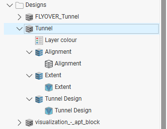
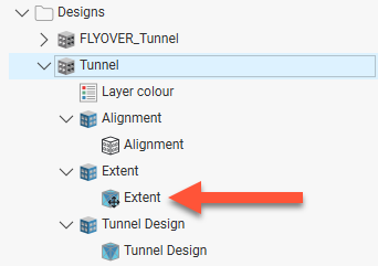
The model will be added to the project tree; expand it to see the different layers. For example, here a Tunnel file has been expanded in the project tree, showing the different layers:
The layer colours are saved in the Layer colour object (![]() ), which you can double-click on to change the colours used.
), which you can double-click on to change the colours used.
The meshes and lines in the model can be used as inputs to geological models and cross sections.
Reloading Designs
To reload a design, right-click on it in the project tree and select Reload. Navigate to the folder containing the design file and select the file. Click Open.
The process is the same as importing the model file. Click OK to reload the data. The original data will be overwritten and dependent objects will be updated to reflect the new data.
Displaying Designs
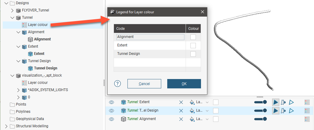
Drag the different layers of the design into the scene to display them. Meshes can be displayed using a Flat colour, the Face dip or the Layer colour. Design lines can be displayed using the Layer colour. Double-click on the Layer colour object (![]() ) in the project tree to change the colours used:
) in the project tree to change the colours used:
Moving Designs
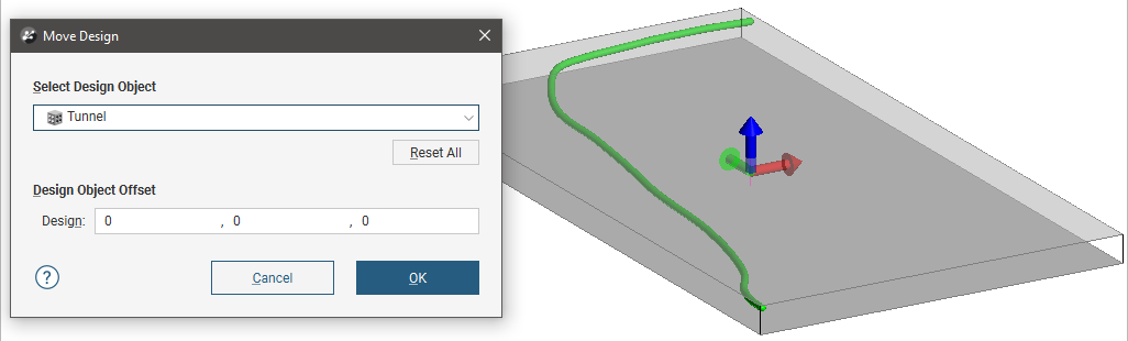
If all or part of the design are in the wrong location, you can move the entire design or part of it. Right-click on the object you want to move and select the Move option. The Move Design window will appear, together with tools in the scene for making changes. Select the part of the model you wish to move from the Select Design Object list. Here the whole model has been selected and there is one set of Offset values displayed in the Move Design:
Click on one of the arrows in the scene to move the design; you can only move in one plane at a time. Updated values will be displayed in the Move Design window.
To move just part of the model, select it from the dropdown list. The controls in the scene will adjust only the location of the selected layer and its contents:

Click the Reset All button to return all location values to 0,0,0.
Click OK to close the Move Design window and save the new values. All parts of the model that have been moved will be marked in the project tree with moved sign (![]() ). For example, here only the extent has been moved:
). For example, here only the extent has been moved:
You can edit the offset values by opening the Move Design window once again.
Working With Design Meshes
You can also carry out standard operations on the design meshes, including the options available for working with meshes described in Cleaning Up a Mesh. Double-click on a design mesh in the project tree to view the options available. Right-click on a mesh to see the other options available.
See Meshes for more information on working with meshes in Leapfrog Works.
A mesh marked with an exclamation mark (![]() ) is not closed.
) is not closed.
Editing Design Lines
If you need to edit a design line, right-click on it and select Extract Polyline. The new polyline object will appear in the Polylines folder. You can then edit the polyline and use it as an input to models and cross sections.
Exporting Designs
Leapfrog Works can export designs and design lines in AutoCAD Drawing file (2013/LT2013) (*.dwg) and Bentley Drawing Files (v8) (*.dgn) formats.
Leapfrog Works can export design meshes in the following formats:
- Leapfrog Attribute Binary Mesh Format (*.msh)
- GOCAD Files (*.ts)
- DXF Files (11/12 [AC1009]) (*.dxf)
- Gemcom Files (*.tri)
- Datamine Files (*.asc, *.asc)
- Micromine Files (*MMpt.dat, *MMtr.dat)
- Surpac Files (*.dtm, *.str)
- DXF Polyface Files (11/12 [AC1009]) (*.dxf)
- Alias Wavefront Object Files (*.obj)
- AutoCAD Drawing Files (2013/LT2013) (*.dwg)
- Bentley Drawing Files (v8) (*.dgn)
Alignments
Leapfrog Works imports LandXML alignments as 3D alignments. The types of LandXML alignment objects that can be imported are lines, curves and the following spiral types:
- Clothoid
- Bloss
- Cubic parabola
- Cubic (JP)
- Sine half-wavelength diminishing tangent curve
The file should have, at a minimum, a horizontal alignment. Chainage information in the imported alignment is taken from the horizontal alignment.
- If the file contains a profile, that will appear in the project as a 3D alignment.
- If the file contains a surface, that will appear as a projected alignment. An alignment can have multiple projected alignments.
To import an alignment, right-click on the Designs folder and select Import Alignments. In the window that appears, navigate to the folder where the alignments file is stored, select the file you wish to import and click Open to start importing the file. If there is more than one alignment in the file, you will be prompted to select which ones to import. Otherwise, the alignment will be imported and added to the Designs folder.
Alignments are organised in the project tree by the imported file. For example, here two files have been imported into Leapfrog Works. The first, 100kmAlignment.xml, contains a single alignment, whereas the file Alignments.xml contains three separate alignments:

The alignments in the parent file object can be expanded to show the separate parts. Here the file imported contains a single alignment, which is made up of a horizontal alignment, a 3D alignment and a projected alignment:

The Projected Alignments folder contains any CAD projections of the alignment that were included in the imported file.
Reloading Alignments
To reload an alignment, right-click on its file in the project tree and select Reload:

Navigate to the folder containing the alignment file and select the file. Click Open. You will be prompted to select which alignments to reload:

Click OK to reload the data. The original data will be overwritten and dependent objects will be updated to reflect the new data. If there are new alignments in the file, they will be added to the existing parent alignment.
Displaying Alignments
When an alignment is displayed, you can change how the chainage values are displayed using the Tick spacing and Label occurrence controls in the properties panel. To hide the chainage values in the scene, disable the text control (![]() ) in the shape list.
) in the shape list.
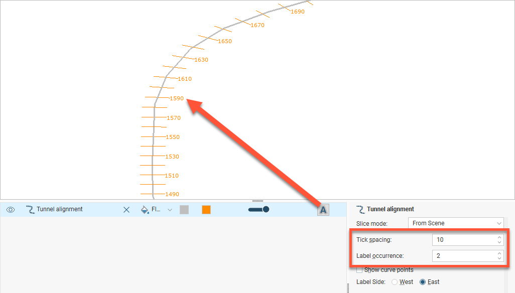
The colour options in the shape list control the alignment colour and the tick mark and chainage values colour:

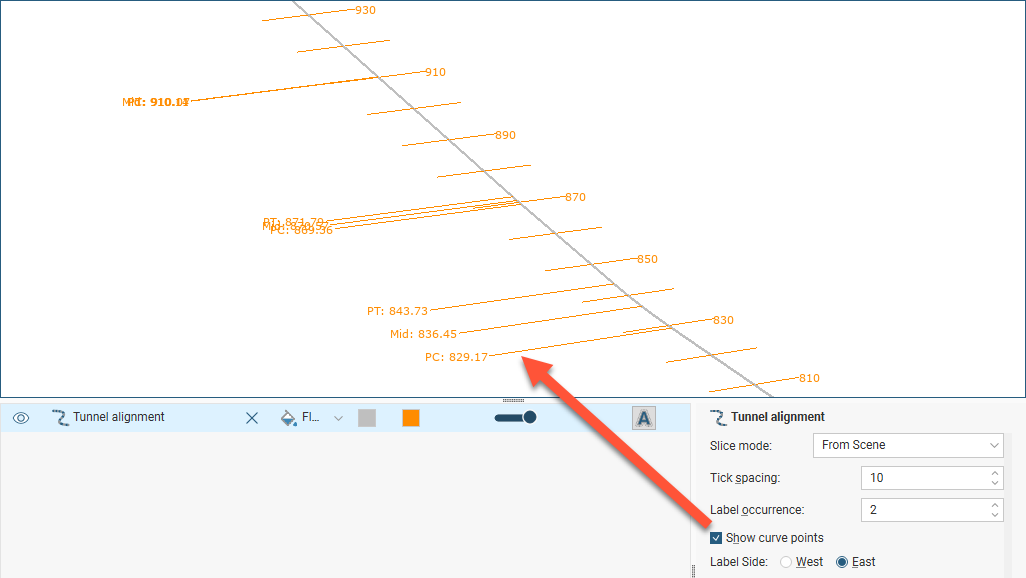
When the chainage values are displayed, there is also an option in the properties panel for showing the curve points.
Using Alignments in the Project
Alignments can be used as the basis for alignment serial sections:

The Start Chainage value used in the New Alignment Serial Section window is taken from the alignment selected, and the Chainage Spacing value is taken from the Tick spacing property in the properties panel:

Note that the link between the alignment’s display properties and the alignment serial section is not dynamic; changing the Tick spacing value does not update the value for the section.
Alignments can be evaluated onto sections as lines:

Got a question? Visit the Seequent forums or Seequent support
© 2023 Seequent, The Bentley Subsurface Company
Privacy | Terms of Use