
Alignment Serial Sections
An alignment serial section can be created using an alignment imported into the Designs folder, a polyline or a GIS line. When creating an alignment serial section from a polyline, you can use an existing polyline or draw a new one.
This topic describes the process of creating and working with an alignment serial section. It is divided into:
- Creating an Alignment Serial Section
- Section Layouts for the Alignment Serial Section
- Displaying an Alignment Serial Section
- Exporting an Alignment Serial Section
Creating an Alignment Serial Section
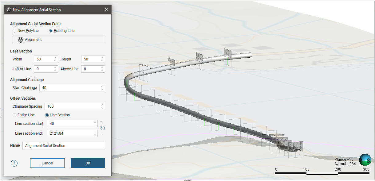
To create an alignment serial section, right-click on the Sections, Plans and Contours folder and select New Alignment Serial Section. The New Alignment Serial Section window will appear. Select whether you will use an existing line or create a new one.
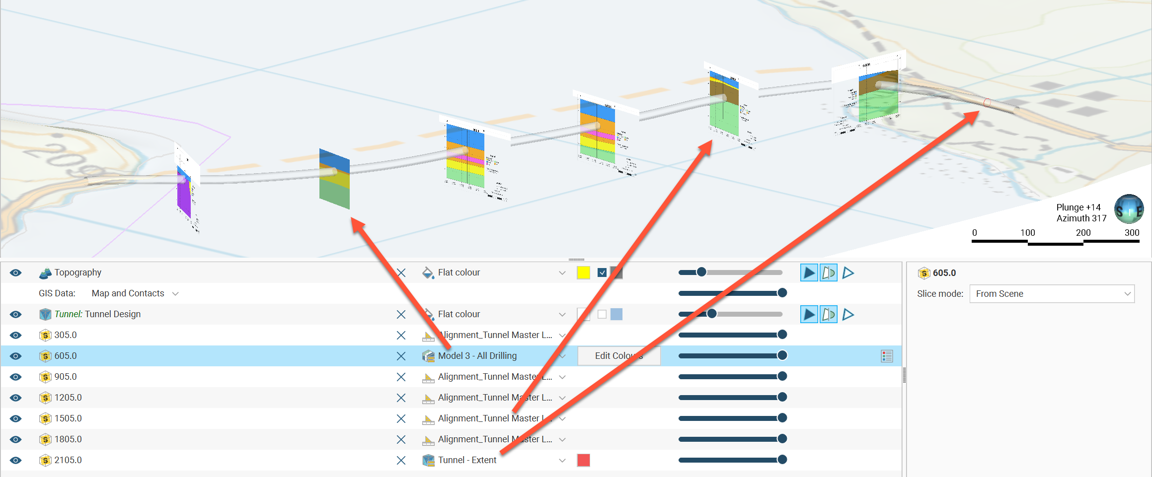
If you select an existing line, planes representing the base section and the offset sections will be added to the scene:
Once you have created an alignment serial section, you can change all settings except the line used.
The Base Section parameters determine the size of the sections using the Width and Height values, and the Left of Line and Above Line settings offset the centre of the section from the line.
Start Chainage defines the measurement for the start of the reference line. If that is considered the zero point, use 0. If another point is the origin for the line, you might wish to set the Start Chainage value for the section as being the offset distance to that origin point. The Line Section Start and Line Section End points make use of this Start Chainage value.
The Offset Sections parameters determine how the sections are distributed along the selected line. Generate sections along only part of the line by selecting Line Section, then changing the Line Section Start and Line Section End.
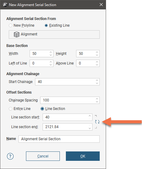
Swap the start and end points of the selected line by clicking the button (![]() ) alongside the start and end settings:
) alongside the start and end settings:
If you have chosen to create a New Polyline, set the Base Section and the Offset Section parameters, then click OK. Drawing controls will appear in the scene and you can begin drawing, as described in Drawing in the Scene.
Once you have finished drawing the polyline, click the Save button (![]() ). The offset sections will be generated and will appear in the project tree. Double-click on the section in the project tree to edit its settings.
). The offset sections will be generated and will appear in the project tree. Double-click on the section in the project tree to edit its settings.
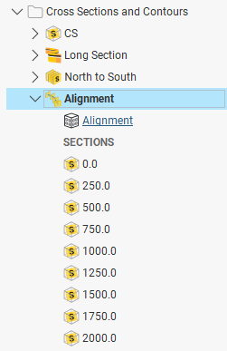
Click OK to create the section. In the project tree, the alignment serial section includes the individual offset sections and the line used to create it:
Section Layouts for the Alignment Serial Section
Create a section layout template for the alignment serial section by right-clicking on the Sections, Plans and Contours folder in the project tree and selecting New Layout Template from the popup menu. Design your section layout template using the section editor tools. Then right-click on the newly-created layout template in the project tree and select Copy Layout Template To, move the alignment serial section from the Available Sections list to the Selected Sections list, and click OK. For a full description on using the section editor and copying section layout templates to sections, see Working With Section Layouts and Layout Templates .
Individual section layouts can then be tweaked, adjusting the location of labels and objects to present each section optimally. Note that changing child section layouts will break the relationship with the layout template and modifications to the layout template will not affect the modified child section layout.
Displaying an Alignment Serial Section
Adding the top-level alignment serial section to the scene will display the section evaluation areas, with the specific evaluations being selectable from the view list. This object cannot be displayed in the scene using the section layouts.
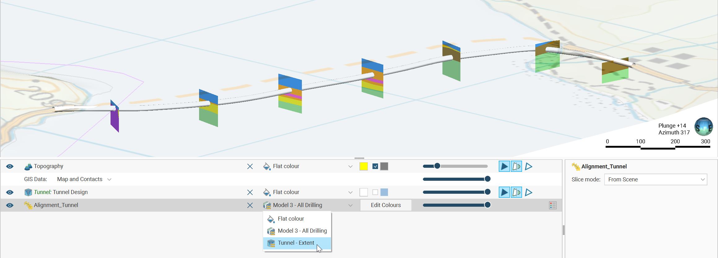
You can, however, add individual offset sections to the scene from the project tree. By default the section layout will be displayed in the scene, but you can also select specific evaluations from the view list.
Exporting an Alignment Serial Section
Alignment serial sections can be exported in the following formats:
- DXF Files (11/12 [AC1009]) (*.dxf)
- AutoCAD Drawing Files (2013/LT2013) (*.dwg)
- Bentley Drawing Files (v8) (*.dgn)
- Industry Foundation Classes 4.3 RC3 (*.ifc)
The DXF format exports a single file with a collection of DXF lines based on intersections between the selected evaluation and the section planes.
The offset sections that make up an alignment serial section can also be exported as a PDF section layout.
For more information on exporting sections, see Exporting Sections.
Got a question? Visit the Seequent forums or Seequent support
© 2023 Seequent, The Bentley Subsurface Company