
Assigning Attributes to Polylines
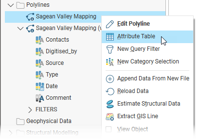
In Leapfrog Works, polylines saved in the Polylines folder have an attribute table that can be opened by right-clicking on the polyline in the project tree and selecting Attribute Table:
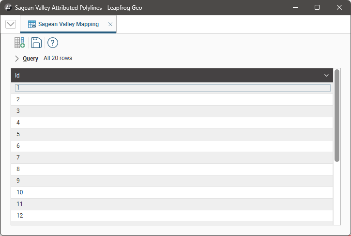
If the polyline has no attributes, the table will contain only the ID column, which is the case here:
Assigning attributes to polylines adds a new column to the polyline table. In this example, a number of attributes have been added to a table; each appears as a column:
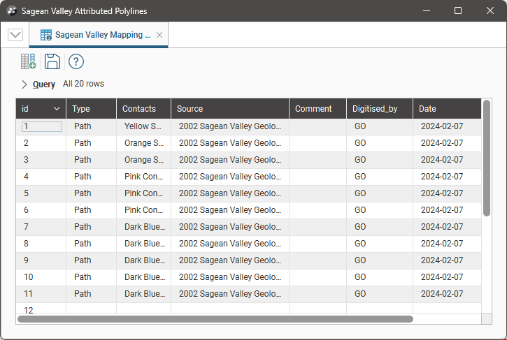
You can edit cell values as well as rename, delete and move columns, as described in the Working With Data Tables topic. However, you cannot edit any columns added via category selection; only attribute columns added within the table are editable.
You can assign attributes to polylines in the attribute table window. For category attributes, you can also assign attributes via category selection. The rest of this topic describes those methods, along with information on editing attributed polylines. See:
- Assigning Attributes in the Attributes Table
- Assigning Attributes Using Category Selection
- Editing Attributed Polylines
Assigning Attributes in the Attributes Table
When a polyline is displayed in the scene and you wish to add an attribute, click on the polyline in the scene and select Edit Attributes from the Scene Details panel. This will open the attribute table and highlight the selected polyline part.
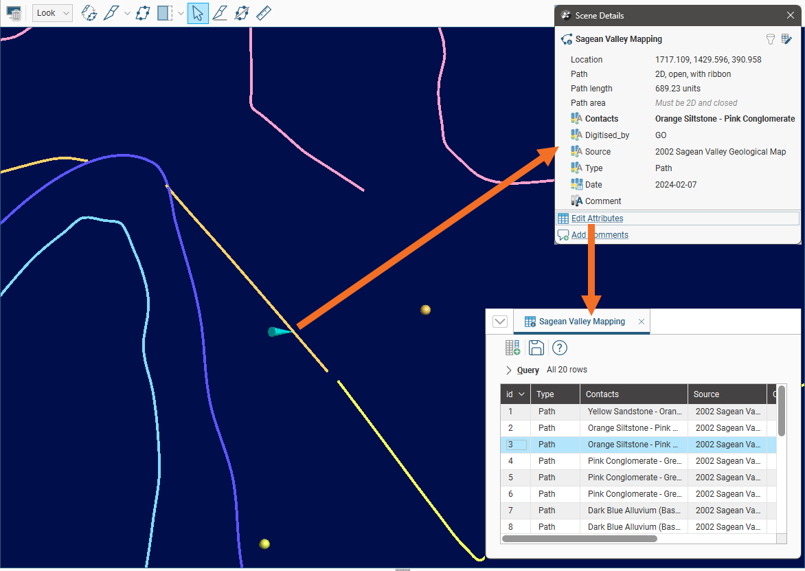
It may be useful to detach the table and have it alongside the scene while you are assigning attributes.
Click the Add new attribute column button (![]() ) to select the attribute type.
) to select the attribute type.
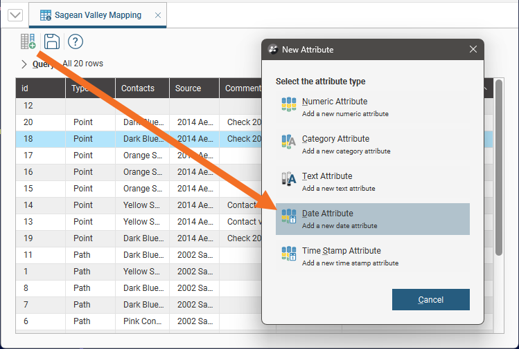
Enter a name for the column and click OK.
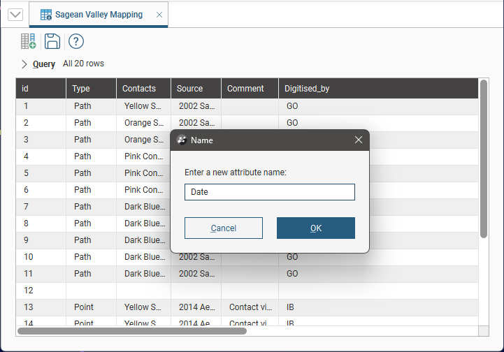
You can then add values for each cell in the new column; click in a cell to edit its content. Recently edited cells are highlighted in bold until the Save button (![]() ) is clicked.
) is clicked.
Attribute information can be exported with IFC geometry.
Assigning Attributes Using Category Selection
Only category attributes can be added to polylines using the category selection tool.
To start adding category attributes to a polyline, right-click on the polyline in the project tree and select New Category Selection. The New Category Selection window will appear:
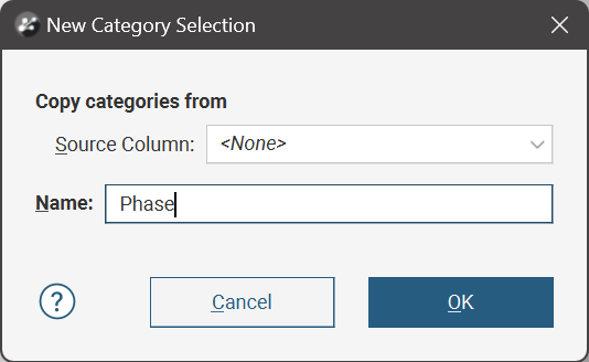
- If you select <None> for the Source Column, a new Name column with no category assignments will be added to the polyline. You can then select polylines and assign them to categories.
- If you select an existing column as the Source Column, the existing column will be linked to the new Name column using the existing data category assignments. You can then select polylines and assign them to existing categories or new categories.
When you click OK, the polyline will be added to the scene along with a set of tools for selecting polyline segments.
The first four tools in the category selection toolbar are the primary tools for selecting in the scene:
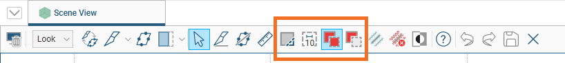
The Select Polylines tool (![]() ) is for drawing across polylines in the scene. This tool adds polylines to or removes them from the current selection, depending on which of the Add Polylines(
) is for drawing across polylines in the scene. This tool adds polylines to or removes them from the current selection, depending on which of the Add Polylines(![]() ) or Remove Polylines(
) or Remove Polylines(![]() ) tools is also enabled:
) tools is also enabled:
- If Add Polylines(
 ) is enabled, drawing across polylines adds them to the current selection.
 - If Remove Polylines(
 ) is enabled, drawing across polylines removes them from the current selection. Drawing across unselected polylines will have no effect.
Selected segments are highlighted in the scene.
You can change the width of the line used by the Select Polylines tool by clicking on the second button in the toolbar:
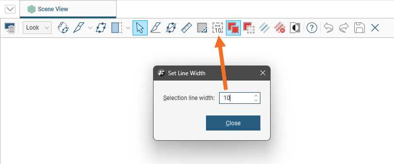
The number shown as part of the Change line width button is the currently set line width.
You can keep this window open while selecting segments so you can increase the line width to choose more segments or reduce the line width to select fewer segments.
You can also:
- Select all visible polylines by clicking on the Select all button (
 ) or by pressing Ctrl+A.
 - Clear all selected polylines by clicking on the Clear selection button (
 ) or by pressing Ctrl+Shift+A.
 - Swap the selected polylines for the unselected points by clicking on the Invert selection button (
 ) or by pressing Ctrl+I.
Click the Assign to button. If there are existing category types, these will appear at the bottom of the list for selection.
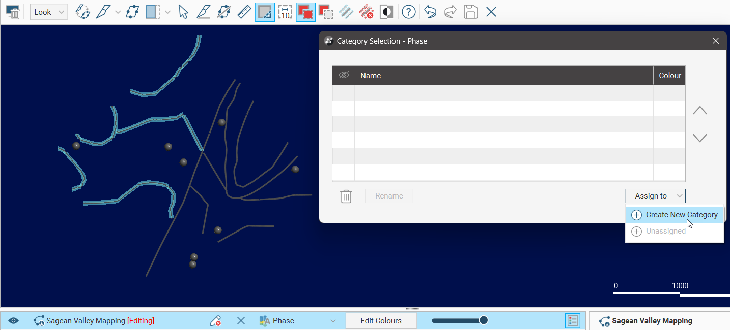
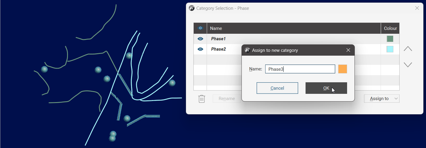
You can also select Create New Category from the options. In the Assign to a new category window, supply a Name for the new category.
When you are finished, click the Save button (![]() ).
).
The new category column will appear in the project tree as an additional column on the polyline table. Select the new column from the shape list to display it.
Editing Attributed Polylines
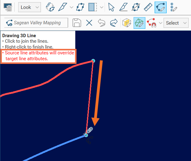
When editing polylines with attributes, you may wish to join two segments that have different attributes. If this is the case, the resulting single polyline can only have one of the original attributes. By convention, the line that you start drawing from when connecting one line to another is regarded as the source line, and its attributes will be preserved.
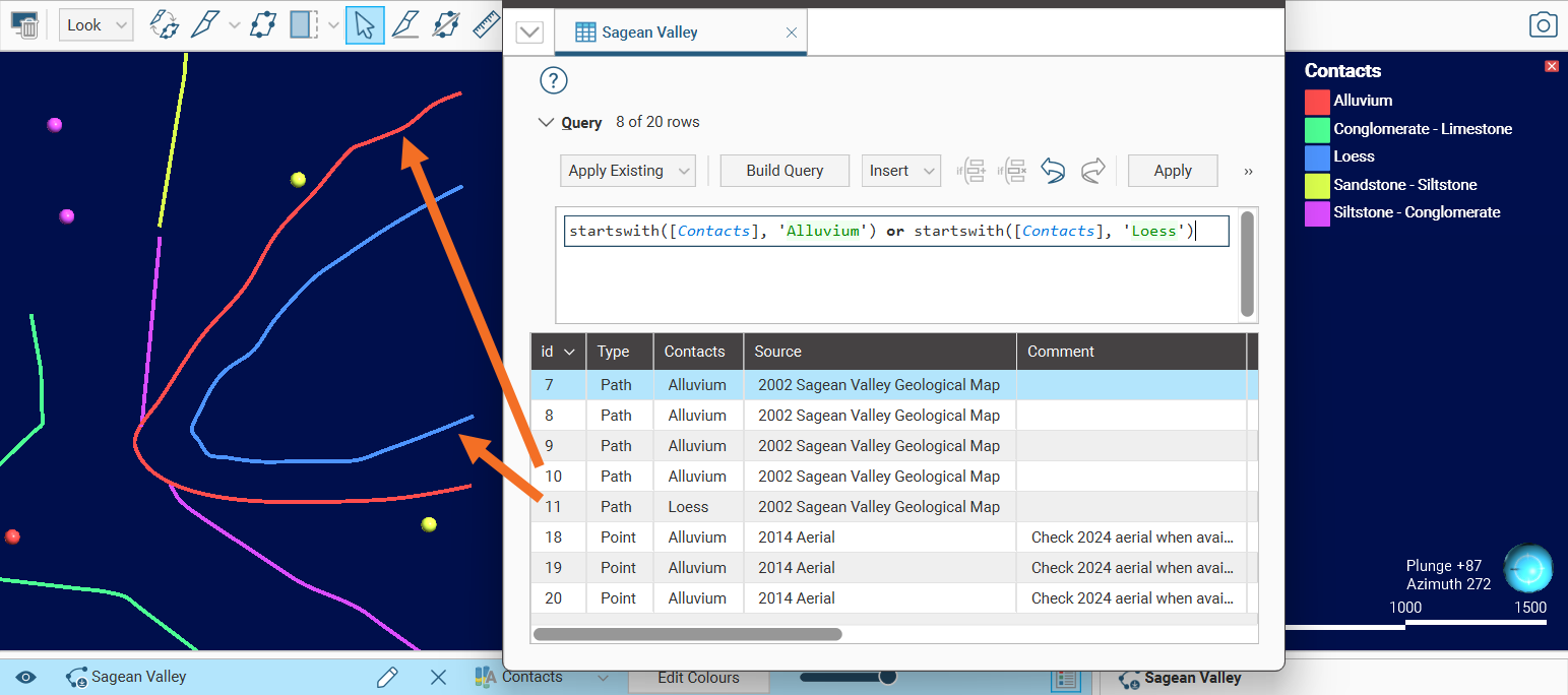
In the following example, the Draw lines tool has been selected and the last node of the red line with the Contact category Alluvium has been clicked on to start a drawing action. The line is being drawn towards the end of the blue line, with the intention to join the two lines. Note that the warning message in red describes what will happen when the action is completed:
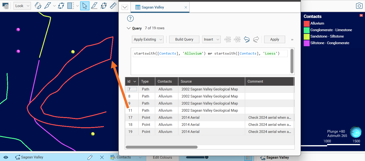
This results in the two lines being joined together into a single line, and the Contact category Alluvium is assigned to this line.
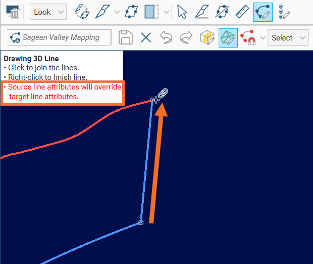
If, however, the line was drawn from the blue line with the Contact category Loess towards the red line, the blue line would have been used as the source line for the attributes:
As a result, the two lines joined together into a single line receive the Contact category Loess:
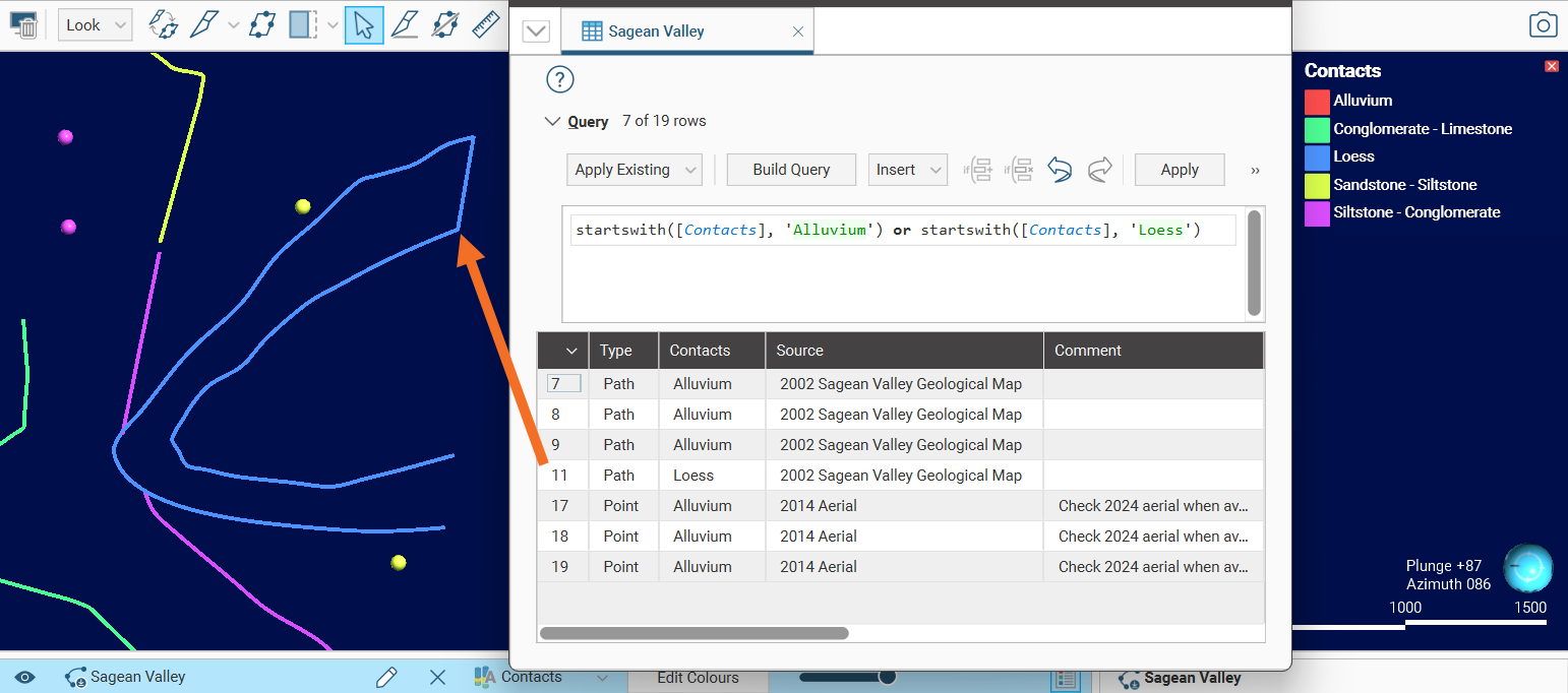
Similarly, if you move a polyline node to link it to another line, the first polyline will be the source line for any attributes to be applied to the resulting polyline.