
Importing, Reloading and Appending Polylines
Polyline formats Leapfrog Works supports include:
- AutoCAD Drawing Files (2013/LT2013) (*.dwg)
- Bentley Drawing Files (v8) (*.dgn)
- Drawing Interchange Polylines Files (*.dxf)
- Leapfrog Polylines (*.lfpl)
- Leapfrog Straight Polylines (*.csv)
- Old Leapfrog Polylines (*.csv, *.txt)
Importing attributes is only supported for polylines in *.csv files.
The rest of this topic describes how to import polylines into Leapfrog Works projects. It is divided into:
Importing Polylines
There are two ways to import a polyline:
- Right-click on the Polylines folder and select Import Polyline. In the Import Polyline window, navigate to the location where the polyline file is saved and select it. Click Open.
- Drag and drop polyline files directly into Leapfrog Works.
If the polyline file is in Leapfrog Polyline *.lfpl format or one of the computer-aided design formats, the importing will start immediately.
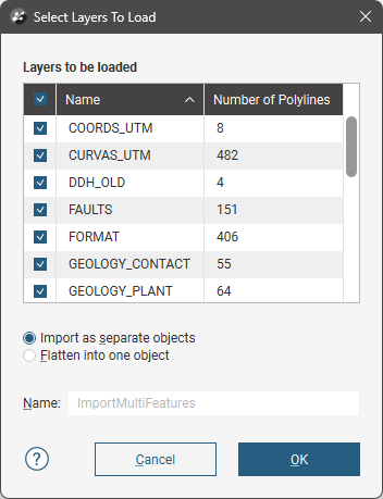
When importing a file that has multiple features, you will be prompted to select which ones to import. You can also choose to:
- Import the features as separate objects. Each feature will appear in the project tree as a separate object.
- Flatten all features into one object. Leapfrog Works will treat all features as a single object.
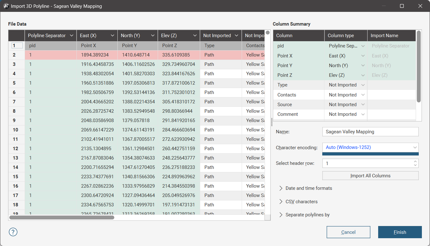
For all the delimited character formats, the Import Polyline window will appear showing the data in the file.
See the Importing Data Tables topic for information on mapping the data in the file to the format Leapfrog Works expects for polylines.
Each polyline consists of a series of vertices, with each row representing a vertex location. Line segments that make up the polyline are drawn between the listed vertices. Vertices that make up each polyline are grouped, with the start of a polyline sequence being coloured red in the Import Polyline window. Subsequent vertices that make up the polyline are coloured green. If there are no green subsequent rows shown in the Import Polyline window, these are points that are treated as polylines, but will appear as points in the scene.
If the format of the data file being imported uses separator rows to group the vertices that make up a polyline, make sure that the Row option is selected under Separate polylines by. Then use Row starts with to specify the character that marks a row as a polyline separator:
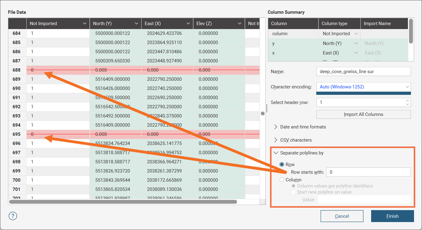
The red highlighted row with the red strike-through line marks the separator recognised by the initial character in the row. The rows between mark the vertices for the line segments of the polyline.
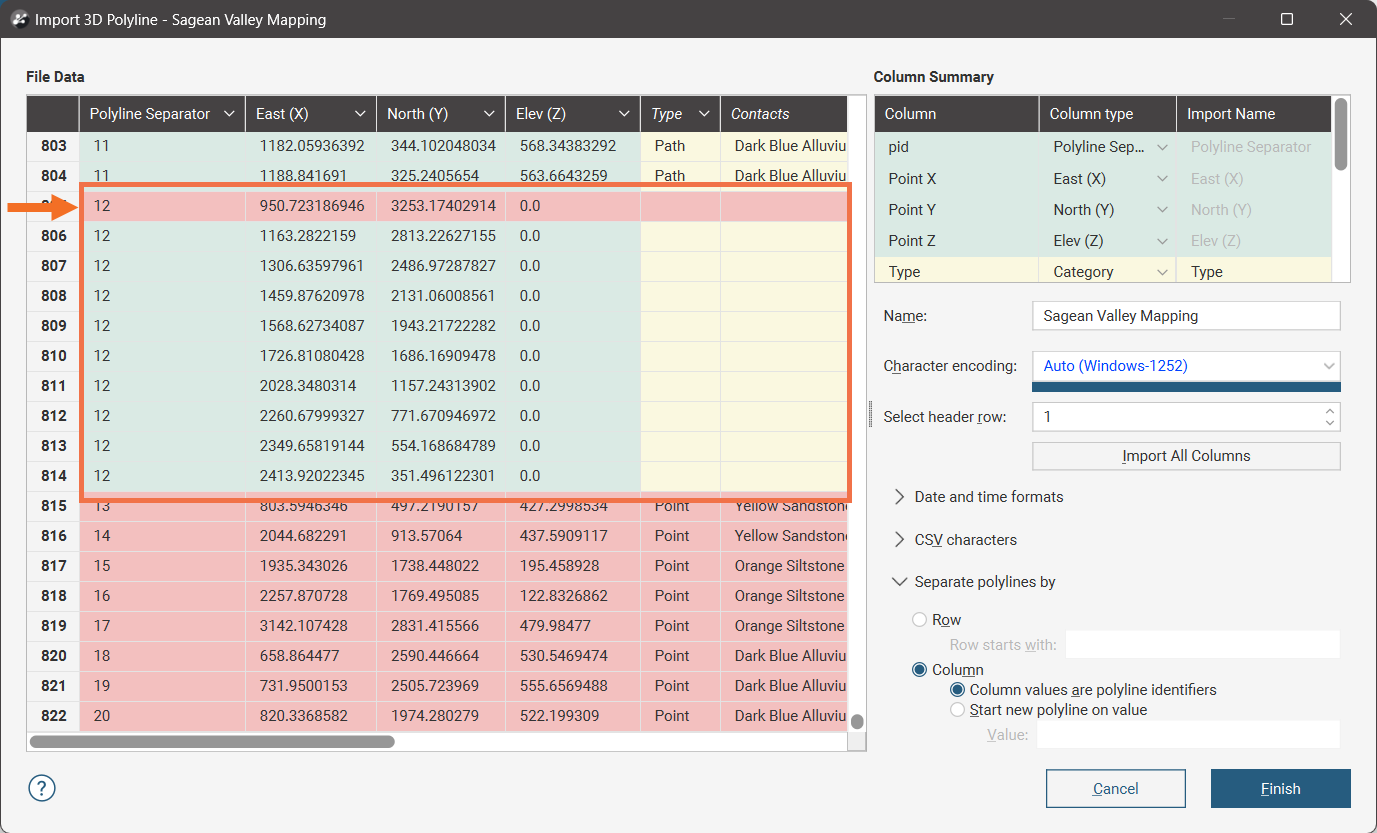
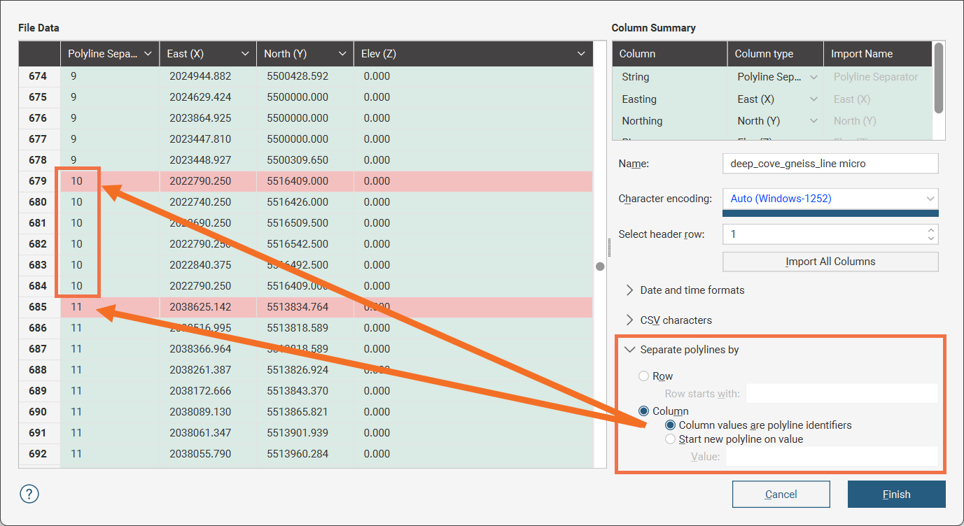
If the format of the data file being imported uses a 'string ID' as a polyline identifier number that each vertex in the polyline shares, make sure that the Column option is selected under Separate polylines by. Then select the Column values are polyline identifiers option to indicate that a data column will store the polyline identifier. If the identifier code for the polylines is not automatically recognised, select Polyline Separator from the dropdown list in the header for the appropriate column. For example, here the red highlighted row marks the starting vertex of the polyline with the string ID 10:
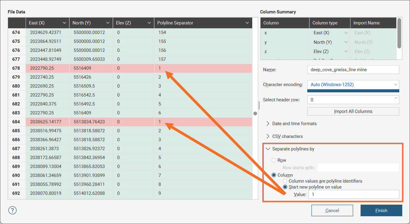
If the format of the data file being imported uses a 'point ID' that marks each vertex in a polyline with a number in sequence, make sure that the Column option is selected under Separate polylines by. Then select the Start new polyline on value option to indicate that a data column will store the point IDs, and specify the value that marks the start of a new polyline, usually 0 or 1. If it is not automatically recognised, select Polyline Separator from the dropdown list in the header for the appropriate column. For example, here the red highlighted row marks the starting vertex of the polyline:
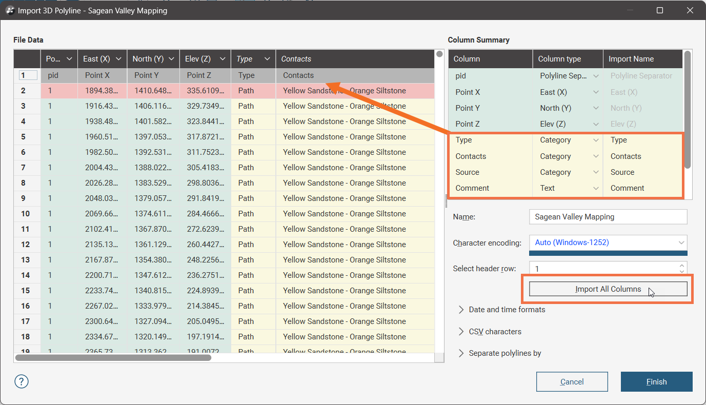
Besides the locations for vertices that make up a polyline, a polyline file can also contain attributes pertaining to the polylines. If these attributes are present as additional columns, each can be added by selecting the appropriate Column type in the Column Summary table. Click the Import All Columns button to automatically add all the additional columns and auto-select column types, overriding the automatic selections if necessary.
The polyline will be imported and added to the project tree under the Polylines folder.
See Using the Polyline Editor for information on drawing and editing polylines.
Reloading Polylines
Reloading data is necessary when the imported data is modified externally. To reload a polyline, right-click on it in the project tree and select Reload Data.
Reloading a polyline discards any changes you have made to the polyline, including any attributes you have added. Any dependent objects will be updated, which can take some time.
Select the file to be reloaded and click Open. The polyline will be updated, as will any dependent objects.
Appending Polylines
If polyline data is stored in multiple files, you can import these files into the project and add them to existing polyline data. To do this, right-click on the object in the project tree that you wish to append and select Append Data From New File. You will be prompted to select a file.
Next, the Append 3D Polyline window will be displayed.
Check the data to ensure that the correct information will be imported, then click Finish to add the new file.
See Adding New Rows to Existing Data Tables in the Updating Tables topic for more information.