
Borehole Planning Groups
With the borehole planner, planned boreholes are created within a borehole group. The advantage of planning boreholes in this way is that all planned boreholes can share a naming convention and default path values. Models can be evaluated onto the group as a whole in order to view drilling prognoses, and some or all boreholes in a borehole group can be exported at once.
Within a borehole group, planned boreholes are defined one-by-one, with the collar or target specified and the path adjusted before moving on to the next hole. When planning a series of boreholes, each subsequent borehole is created offset from the previous borehole. The offset distance can be changed in the Borehole Planning Options window.
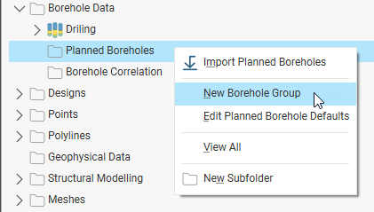
Start by right-clicking on the Planned Boreholes folder and selecting New Borehole Group:
This topic describes how to define planned boreholes within a borehole group, view drilling prognoses and export planned boreholes in different formats. It also describes how to import planned boreholes into an existing borehole group or into a new group.
The rest of this topic is divided into:
- Working With Borehole Groups
- Setting Borehole Planning Defaults
- Adding Planned Boreholes
- Viewing Drilling Prognoses
- Exporting Planned Boreholes
- Importing Planned Boreholes
Working With Borehole Groups
A borehole group acts as a container for the boreholes in a drilling campaign.
Creating a Borehole Group
To create a borehole group, right-click on the Planned Boreholes folder and select New Borehole Group. In the Borehole Group window, you can change the Prefix that will be used in naming each borehole that will be added to the group.
Displaying Planned Boreholes
Once there are planned boreholes in the group, you can display the group in the scene. Do this by dragging the group from the project tree into the scene. To control what boreholes are displayed in the scene, open the group and use the show/hide buttons (A):
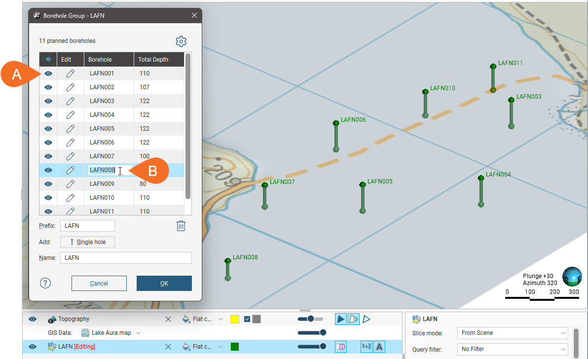
You can edit a borehole‘s name in this window by double-clicking on it (B).
Search for planned boreholes in the list by pressing Ctrl-F. A Find window will appear that you can use to search the list.
To update a borehole, click its Edit button.
Deleting Planned Boreholes
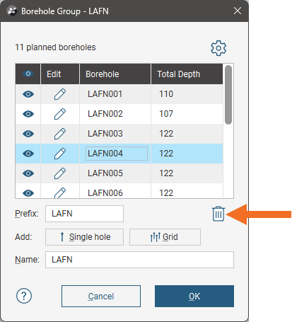
To delete a planned borehole, click on it in the list, then click the Delete button:
Moving Planned Boreholes to Another Group
You can move planned boreholes to a different group by opening both groups, then dragging boreholes between the groups.
For example, here the boreholes selected in the first group are being copied into the second group:
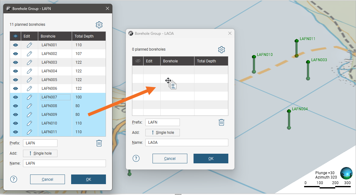
This makes copies of the selected boreholes in the other group without removing them from the original group. You will need to delete the planned boreholes from the group you copied them from.
Evaluating Models on Planned Boreholes
Any model in the project can be evaluated on a borehole group, and evaluations can be exported when the group is exported as interval tables. See Exporting Planned Boreholes. Right-click on the group in the project tree and select Evaluations. The Sample Distance setting applies to numeric evaluations and determines the spacing between downhole evaluation points.
Defining Filters for Planned Boreholes
You can also define filters for a borehole group. A filter makes it easier to select a subset of the boreholes when the group is displayed in the scene. To define a filter, right-click on the group and select New Filter. Select which boreholes to include in the filter and enter a name for it. The filter will be saved in the project tree as part of the group.
Setting Borehole Planning Defaults
Borehole planning defaults are set on a per-project basis, and when you are starting to plan a new drilling campaign, it is a good idea to update the default drilling values before you start adding boreholes to a group. You can do this from the Borehole Group window by clicking the settings button (![]() ):
):
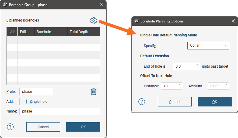
There are two planning modes available:
- Collar. The collar serves as the starting point in defining the borehole. This mode suits scenarios where the drilling site is the primary constraint. Specify the collar’s location, dip and azimuth, along with the path. The target’s parameters will be calculated using the collar and path parameters. You can define the collar’s location by clicking in the scene or by entering the coordinates in the Borehole Planning window.
- Target. The target serves as the starting point in defining the borehole. This mode suits scenarios where drilling to a particular contact, zone or depth is the primary consideration and the collar location is not the primary constraint. Specify the target and its path; the borehole‘s collars parameters will be calculated from the target and path. You can define the target’s location by clicking in the scene or by entering the coordinates in the Borehole Planning window.
Choose which mode you will be using for the borehole group.
The Default Extension is the length by which the borehole extends past the Target location.
The Offset To Next Hole values apply when defining multiple boreholes in the Borehole Planning window.
Enter the information required and click OK. The new settings will be applied to the next new planned borehole added to a borehole group.
Adding Planned Boreholes
To start planning a borehole, add the data objects to the scene that you will use in defining the planned boreholes, such as any existing boreholes and surfaces that represent the collar and target locations. Open an existing borehole group or create a new one by right-clicking on the Planned Boreholes folder and selecting New Borehole Group.
Set the Prefix to be used for each borehole that will be added to the group, and update the drilling defaults, if necessary.
To add the first borehole, click the Single hole button (A). This opens the Borehole Planning window (B), with an initial borehole displayed in the scene (C).
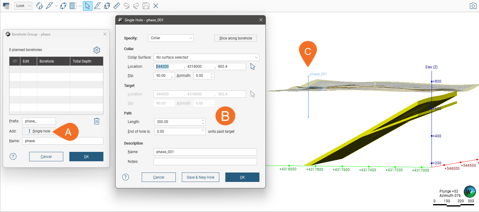
The new borehole has a Name that uses the Prefix set in the Borehole Group window. You can add a Note about this borehole that will be visible in the scene details panel when the borehole is clicked on in the scene.
This initial borehole uses the default planning mode and the parameters set for the project in the Borehole Planning Options window.
As you work in this window, note that the changes you make to:
- The planning mode
- The Collar Surface
- The Path settings
will be retained when you click Save & New Hole in order to create another borehole. This makes it easy to set up a series of planned boreholes. You can change the default values used for the first borehole in the Borehole Planning Options window.
There are two planning modes you can use in this window, specifying the Collar or specifying the Target.
The planning mode determines which parameters you can change in this window:
- For Collar mode, you cannot edit the target’s settings, which are calculated from the collar and path settings.
- For Target mode, you cannot edit the collar’s parameters, although you can choose a Collar Surface that will be used in setting the collar elevation.
To specify the collar or target location you can:
- Enter coordinates in the Borehole Planning window.
- Click on the button for the collar/target and then click in the scene where you wish to add the collar/target.
Entering coordinates and clicking in the scene both set the collar or target location in the scene and display a path calculated using the parameters in the Borehole Planning window. In both cases, drawing a slice in the scene can help in adjusting the borehole and in defining subsequent boreholes. To do this, click the Slice along borehole button
You can also use the collar/target button to ‘draw’ the path of the borehole in the scene. To do this, click the button for the collar/target, then click in the scene without releasing the mouse button. Drag to define the Path and release the mouse button when you have reached the target.
Once you have finished defining the borehole, you can save the borehole and close the planning window or keep the planning window open and create a new borehole.
- To keep adding boreholes to the borehole group, click Save & New Hole. The current borehole will be saved and the Single Hole window will open for a new borehole created at the Offset To Next Hole distance specified in the Borehole Planning Options window. The planning mode, Collar Surface and Path settings used will be those used for the previous hole.
- To close the current borehole, click OK. The borehole will be saved to the group and its window closed, returning you to the Borehole Group window.
Here the planning mode (D) is Collar and the initial Location values (E) create a borehole in the scene (F):
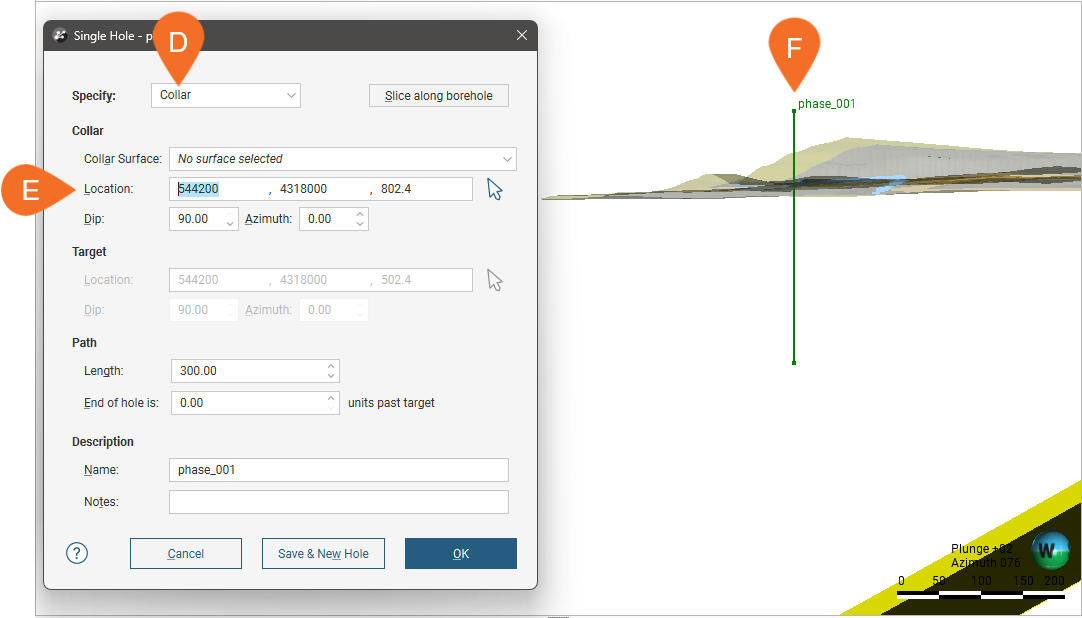
Note that the collar location is above the topography surface displayed in the scene. To make sure the location lies on the topography, select a surface from the Collar Surface list (G):
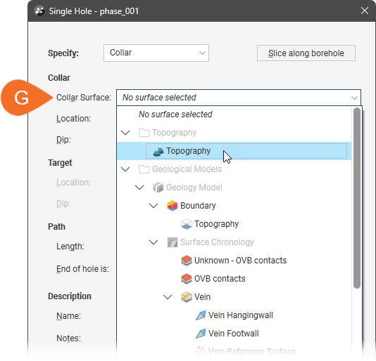
This moves the collar onto the selected surface.
Viewing Drilling Prognoses
Planned boreholes can be evaluated against any model in the project. To view drilling prognoses for a borehole, right-click on a borehole group in the project tree and select Drilling Prognoses. The Drilling Prognoses tab will appear:
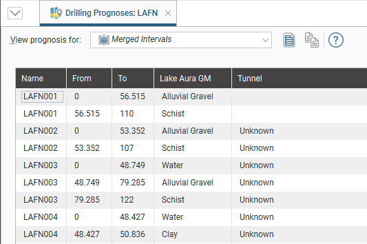
The dropdown list contains all evaluations on the borehole group, along with a Merged Intervals option that combines the information from all evaluations. You can copy the information displayed to your computer’s clipboard by selecting rows, then clicking the Copy button (![]() ). The information in the selected rows will be copied as tab-delimited text, which can be copied into a spreadsheet application such as Excel.
). The information in the selected rows will be copied as tab-delimited text, which can be copied into a spreadsheet application such as Excel.
Exporting Planned Boreholes
There are three ways to export planned boreholes:
Export Planned Borehole Parameters
Exporting planned borehole parameters exports the boreholes as a *.csv file. To export parameters for planned boreholes, right-click on a borehole group and select Export Parameters. In the window that appears, select the boreholes you want to export. The total length will be updated as you add or remove boreholes.
You can constrain the list of boreholes to be exported using an existing Query Filter.
In Leapfrog Works, positive dip points down for planned boreholes. To invert the dip for exported planned boreholes so that negative dip points down, tick the box for Invert dip on export.
Click Export. Navigate to where you wish to save the file, then click Save.
Export as Polylines
Planned boreholes can be exported as polylines in the following formats:
- Leapfrog Polylines (*.lfpl)
- Leapfrog Mining Polylines (*.csv)
- Drawing Interchange Polylines Files (*.dxf)
- Surpac String Polyline Files (*.str)
- Gocad Polylines Files (*.pl *.ts)
- MineSight Polylines Files (*.srg)
- Datamine Polylines Files (*.asc)
- Micromine Polylines Files (*.str *.asc)
- AutoCAD Drawing Files (2013/LT2013) (*.dwg)
- Bentley Drawing Files (v8) (*.dgn)
To export planned boreholes as polylines, right-click on a borehole group and select Export as Polylines. In the window that appears, select where you wish to save the file, enter a file name, select the file type from the Save as type options, and then click Save.
Export as Interval Tables
In order to export planned boreholes as interval tables, you must first evaluate at least one model on the borehole group. Once you have done this, right-click on a borehole group and select Export as Interval Tables.
Select the evaluations you wish to include, then click Export. In the Export Planned Boreholes window, the files that will be created are listed, one each for the collar and survey table and one for each selected evaluation. Change the Base file name, if required, choose a folder in which to save the files, then click Export to save the files.
Importing Planned Boreholes
Leapfrog Works can import planned borehole geoscience objects from Seequent Evo. The boreholes must be single-segment holes that have no deviation or are naturally deviated. If any planned boreholes could not be imported, a message will be displayed. For more information on importing objects into Leapfrog Works from Seequent Evo, see the Importing Data from Seequent Evo topic.
Leapfrog Works can also import planned boreholes from files in CSV format. The columns expected are:
- A borehole identifier
- X-Y-Z coordinates for the planned borehole
- Azimuth
- Dip
- Distance
- Extension
- Target Depth
- Comment
When importing planned boreholes, you can import them into a new group or into an existing group. To import planned boreholes, right-click on the Planned Boreholes folder or on a group and select Import Planned Boreholes. If the IDs in the file are already in the project, you will be prompted to resolve the conflict:
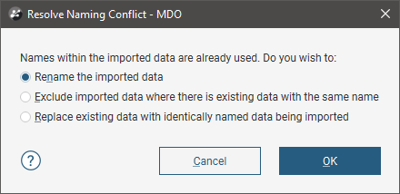
You can:
- Rename the imported boreholes. Leapfrog Works will automatically assign new names and import the planned boreholes.
- Exclude planned boreholes that already exist in the project. Planned boreholes will only be imported if they have an identifier that does not already exist in the project.
- Replace existing planned boreholes with the imported boreholes. Use this option if you are importing information previously exported from the project and subsequently updated in an external application.
Click OK to process the file.
If there are no conflicts, the planned boreholes will be added to the project.