Polarity in Leapfrog Works
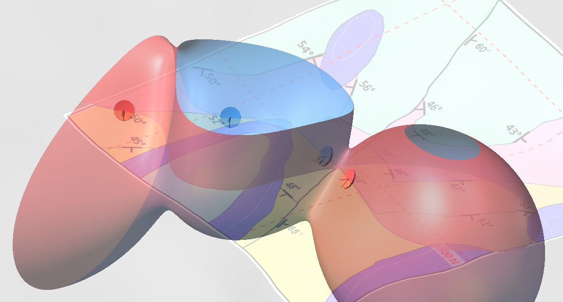
Polarity refers to which side of an object is considered the “inside” or “outside”, or the “younger” or “older” side. When used correctly, polarity is a useful tool for controlling structurally complex surfaces, defining how custom boundaries are applied to models or controlling how meshes are clipped during mesh operations. Object polarity can cause unexpected or confusing results if the polarity of an object is different to what was intended or expected.
Polylines, surfaces and structural data all have polarity in Leapfrog Works.
Polarity and Polylines
When a polyline is drawn on a two-dimensional plane such as the slicer, the orientation of the polyline will be consistent. When a polyline is drawn on a three-dimensional object, however, each segment in the polyline will have a different “in” and “out” orientation. To see the line polarity, and the polyline to the scene and increase the Ribbon width so a clear ribbon extends away from the polyline. This will help you to see not only how a line changes direction, but also how it twists. You can view the Surface ribbon ( ) as shown here:
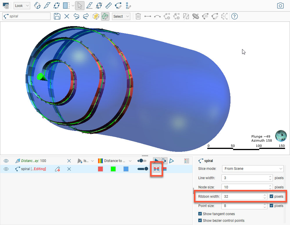
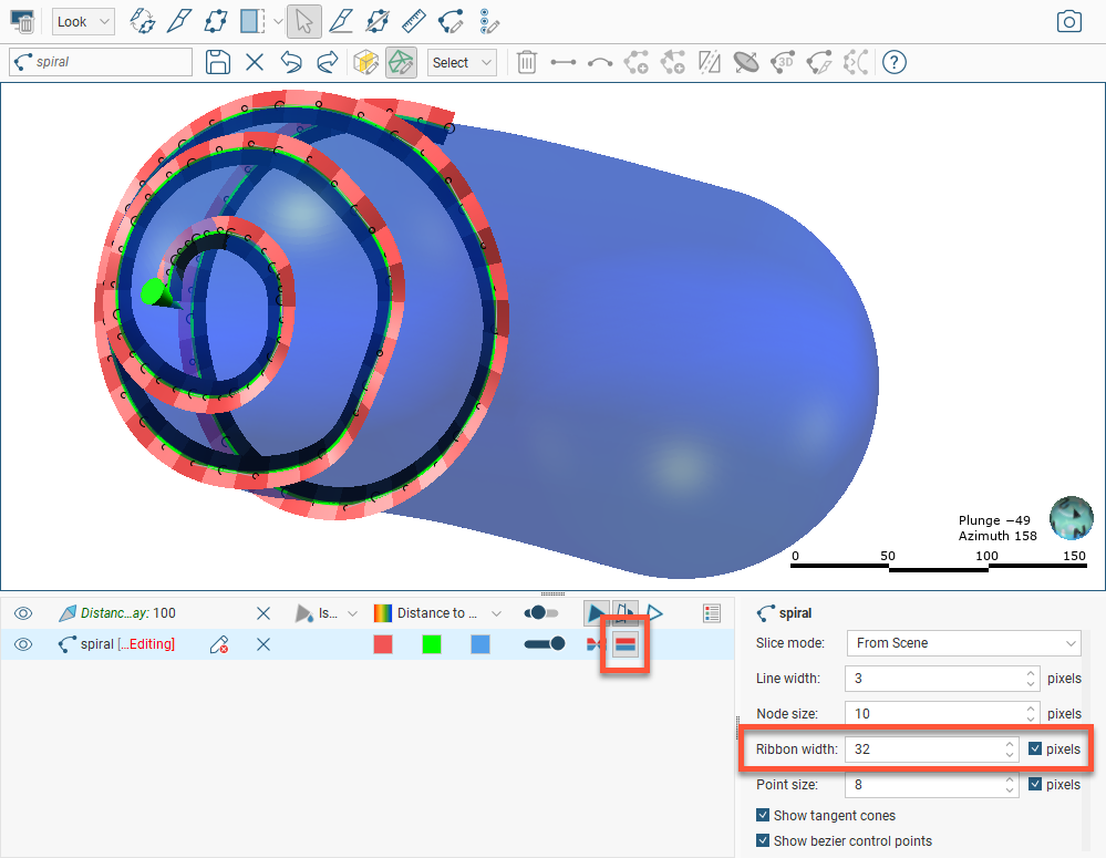
Or you can choose the Normal ribbon ( ), which depicts the ribbon at the normal (or, right angles to) the Surface ribbon view:
Invert Polyline Polarity
If the whole line has the wrong polarity, you can select the line then click the Flip selected objects button ( ).
Adjust Polyline Polarity Using Tangents
To adjust a portion of a polyline, one tool you might choose is the Add or set tangents at the selected points, from the current viewing angle button ( ). Click on the line where you would like the tangent inserted, then click the () button. This will add a tangent pointed directly away from the current viewing perspective, and whole line will be twisted so the surface ribbon is aligned in the direction of the viewing angle also, up to the point that some other part of the ribbon has an existing tangent set (if any).
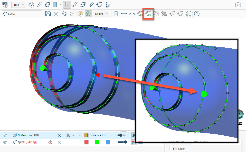
To achieve the desired result, you may need to reposition the viewing angle and set additional tangent points.
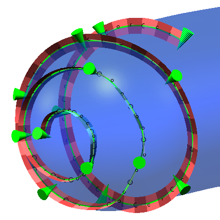
Imported polylines can often have inconsistent polarity across different parts of the polyline, which can limit their usefulness until the polarity issues are addressed. Observe how a inverted polarity direction in one part of a polyline can affect a mesh built from the polyline:
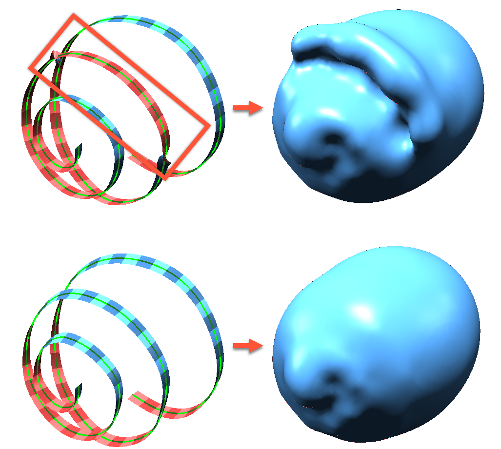
If you are editing a surface with a polyline and you get an unexpected result such as the one shown above, check the polarity of your polyline disks.
Polarity and Surfaces
Almost every mesh added to the scene in Leapfrog Works, including meshes from the Meshes folder or surfaces from a geological model, will have one colour on one side of the surface and a different colour on the other side. This represents the polarity of the surface, identifying what is considered the ‘outside’ and the ‘inside’ of the surface. Note that numeric model isosurfaces and form interpolant surfaces do not have polarity.
When a surface from the Meshes folder is added to the scene, by default the colouring is red for the inside and blue for the outside of the mesh.
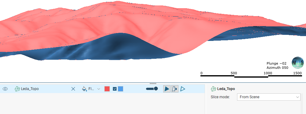
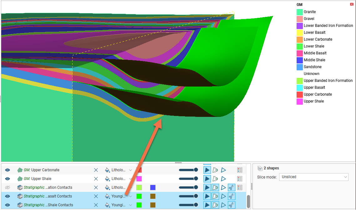
When a surface from a geological model is added to the scene, the colours reflect the relevant unit colours defined by the drilling data, and the polarity represents the “younging” side. Here two surfaces separating some stratigraphic layers are revealed, and each side of the surface is coloured by lithology:
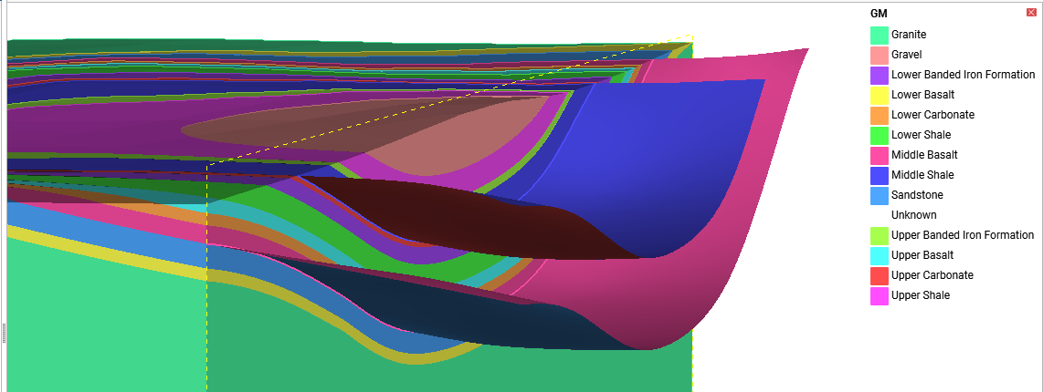
In addition to the surfaces being displayed coloured by the lithologies assigned to each side, they can also be displayed by their younging direction, which is shown here, where the green side is the younger side and the brown side is the older side:
Polarity and Structural Data
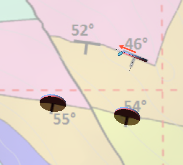
The polarity of structural data is also indicated by the colouring of the disk sides. The orientation of a structural data disk is initially set when it is drawn, according to the direction the mouse was dragged after clicking on the place to insert the disk:
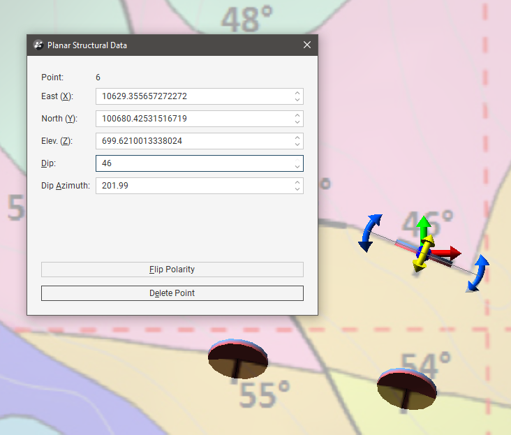
Then the tilt of the disk is set in the Planar Structural Data window. Note also the Flip Polarity button to invert the orientation of the disk if the disk was accidentally drawn in the wrong way.
Consistency of polarity is important to get a consistently oriented surface created from the structural data, a surface with a clear ‘inside’ and ‘outside’.
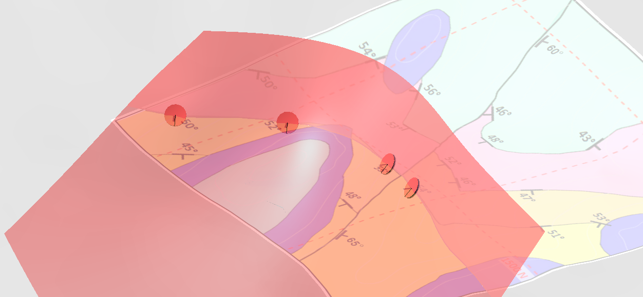
Where structural data has been placed with inconsistent polarity, any resulting surface will have a contorted and inappropriate shape due to unclear ‘inside’ and ‘outside’ directions. If you are editing a surface with structural data and you get an unexpected result such as the one shown below, check the polarity of your structural data disks.