
Adding and Styling Lines
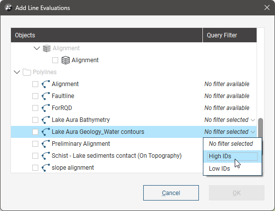
The Lines folder contains all lines that have been added to the section layout. To add another line, first make sure it has been evaluated on the section, then right-click on the Lines folder and select Add Line. Select from those available, select a query filter if available and desired, then click OK.
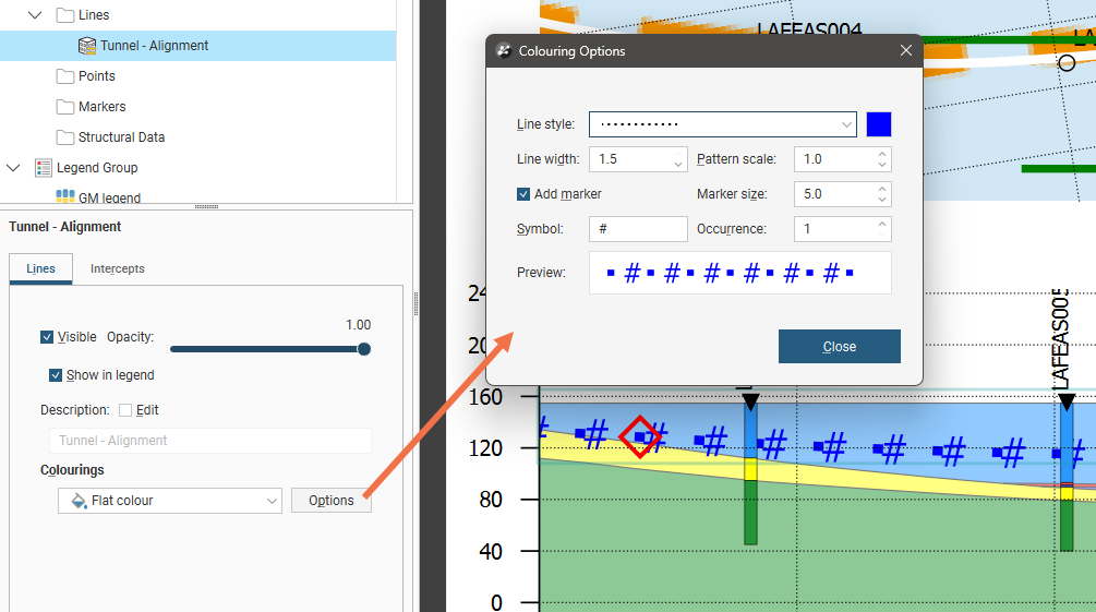
In the layout tree, click on the line object to view line styling options. Visibility can be turned on or off and the Opacity of the projection of the line onto the section can be set. Edit the text used to display the line by enabling the Edit box and then changing the text. You can change the Line style, Line width, Pattern scale and colour. You can also define a marker to display along the line by enabling Add marker and then specifying a Symbol to use. Increasing the Occurrence number increases the gap between symbols. A Preview is displayed and the surface will be updated in the section preview.
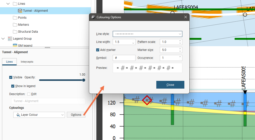
For design lines, under Colourings you can also select between a Flat colour option that can be selected and changed in the Colouring Options window by clicking the colour tile and using the colour picker, or you can choose Layer colour to use the same line colour used in the scene and modified using the colour selector in the shape list.
If your polyline has category attributes, you cannot use the category data to directly apply colouring to polylines you add to the section layout.
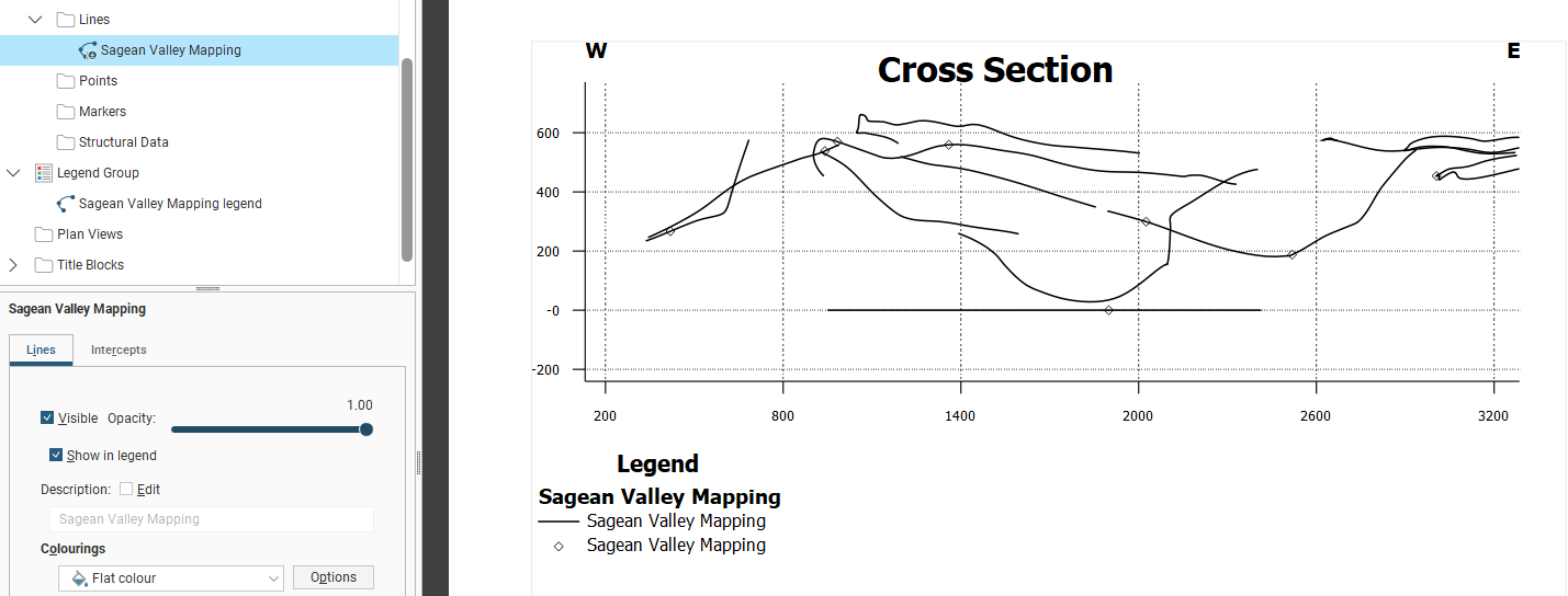
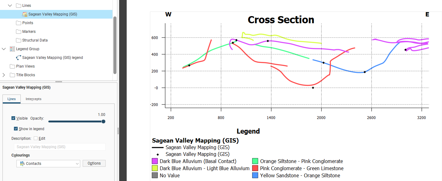
You can, however, right-click on the polyline and select Extract GIS Line, and add the GIS line to the section layout. While a GIS line will not contain points or tangents, it can be used to specify a category for Colourings.
Alignment lines have a Chainage tab in which you can style and place the tick marks and labels:
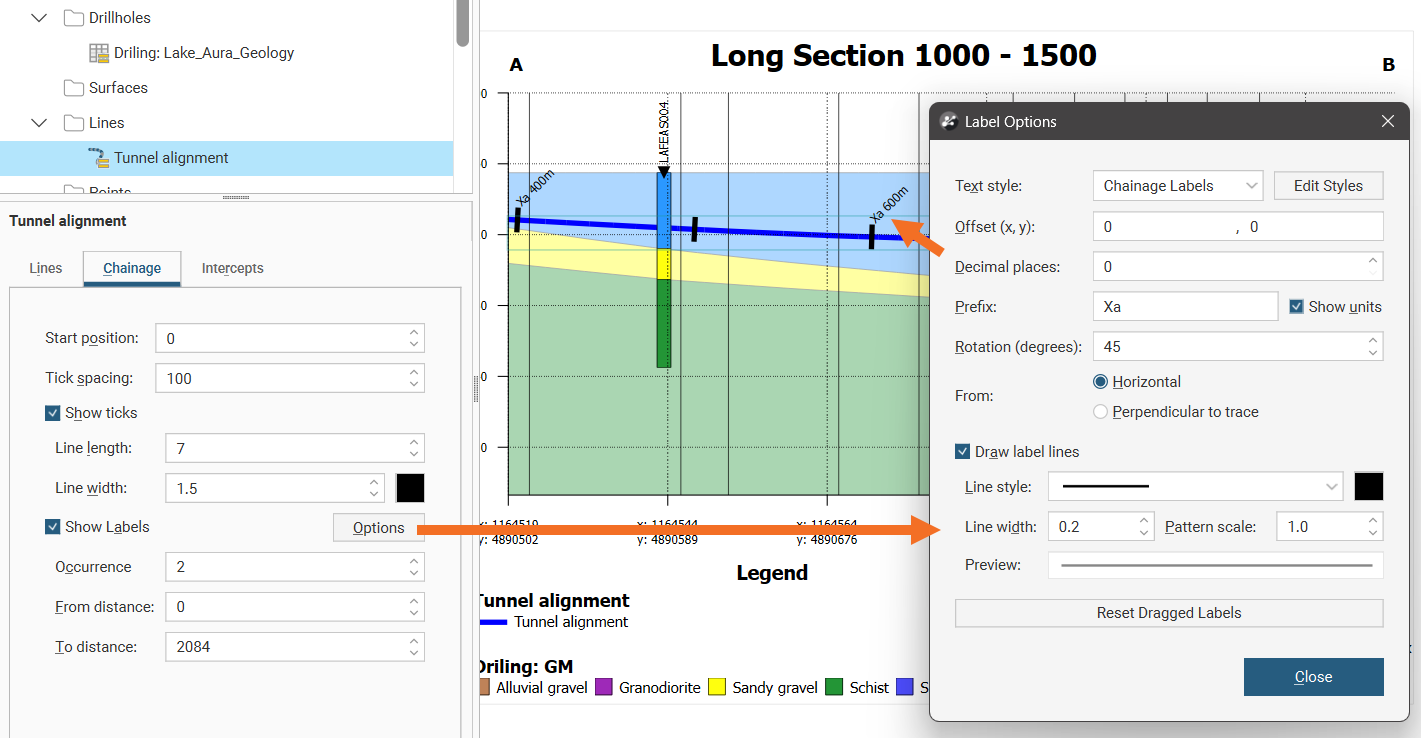
The Occurrence value controls how often labels will appear. Choose 1 for the label to appear on every tick, 2 for a label to appear on every second tick, and so on. The From distance and To distance values will constrain the region where labels will appear to only a region of interest.
In the chainage Label Options window, the Prefix can be used to add characters in front of the chainage distance, perhaps to indicate a particular named reference point that the distance relates to. You can also choose to Show units as part of the label. Other label positioning and styling controls are similar to other layout elements.
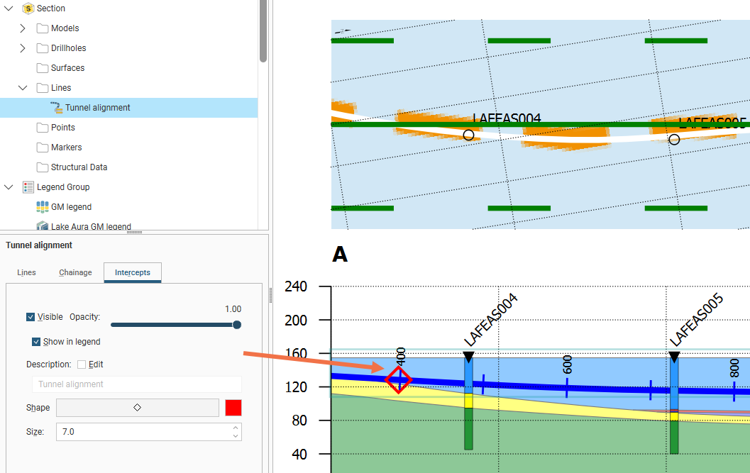
Switch to the Intercepts tab to style the pierce points where the line intersects the section. The point Shape can be selected from a set of 60 options, the Size can be set and the colour changed by clicking the colour tile and selecting a new colour using the colour picker.
To set the clipping distance for a line projected onto a section, double click on the line object or right-click on it and select Projection settings. Then set the Clip by minimum distance to section plane value.
Lines can be added to both the section and strip views, but the projection of the line onto the strip view cannot be clipped to a distance as it can be for sections and plan views.