
Adding and Styling Models
The Models folder contains all models that have been added to the section layout. To add another model, right-click on the Models folder and select Add Model. Select from those available and click OK.
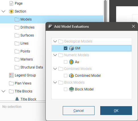
When you display multiple models on the section, you can end up with a large number of objects that obscure the information you want to emphasise. You can:
- Use the Opacity setting for each model to expose and emphasise information.
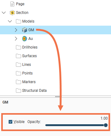
- Right-click on the models and select an option to move them up or down in the layer hierarchy.
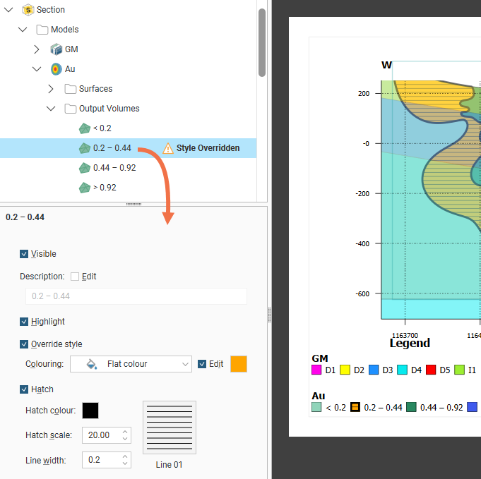
- For geological models, numeric models and combined models, expand the model in the layout tree to change how each output volume is displayed. You can hide volumes by deselecting the Visible setting, or tick Highlight to increase the weight of some of the output volumes. You can use an automatically selected flat fill colour or set a specific flat fill colour. For numeric models, if you override the style of a volume, you can also use the colour associated with the data column and a selected colourmap. Hatching patterns and colours can be added and customised.
Numeric model isosurfaces or output volumes can be coloured according to the colouring options for the parent object in the scene. To do this, override the style for the object then select the column to use for the colouring. You can then choose from the colourmaps available.
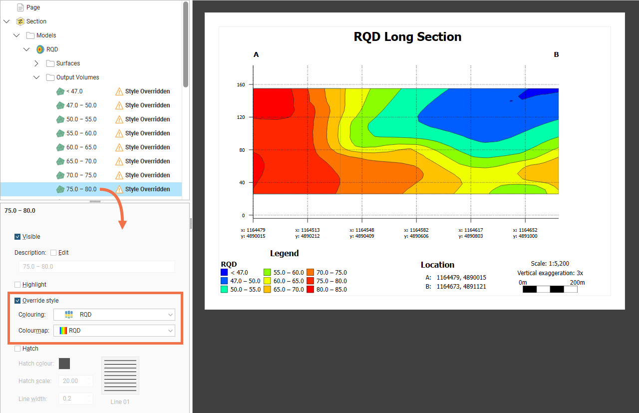
Whenever the colourmap of the parent object is updated in the scene, the colourmap will also be updated on the section layout.
- For flow models and block models, you can choose the column used to colour the model and filter the values colouring the model or select which categories colour the model.
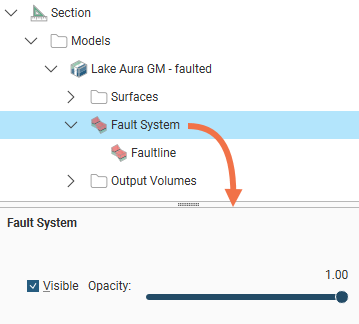
If a geological model with an active fault system is added to the section layout, it will include a Fault System that contains all the active faults in the model. Click on the Fault System to control whether or not it is Visible and to set its Opacity:
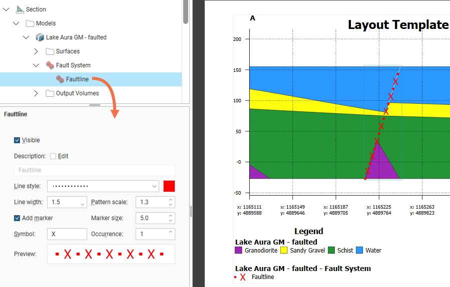
Click on the individual faults to control how they are displayed. Edit the fault’s Description by enabling the Edit box and then changing the text. You can also change how the fault is displayed, including the Line style, Line width, Pattern scale and colour. You can also define a marker to display along the line by enabling Add marker and then specifying a Symbol to use. A Preview is displayed and the fault will be updated in the section preview:
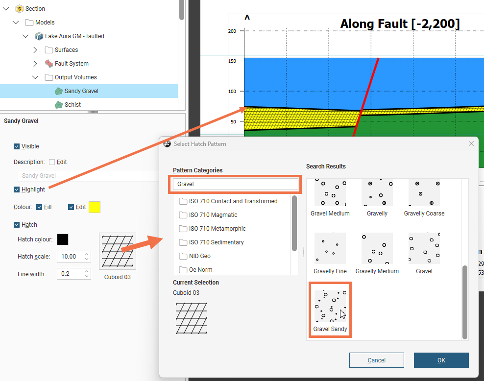
For the volumes in the Output Volumes folder, click on a volume in the layout tree and then change the volume properties. A single line style is used to display a model’s output volumes. There is, however, a Highlight option that can be enabled to make a volume of interest stand out from the other volumes. The swatch colour can be modified by ticking Edit then clicking the colour tile to open the colour picker tool. Swatches for output volumes can also be displayed using a hatch instead of, or in addition to, a colour fill. To do this, enable the Hatch option and click on the sample to select from the available patterns. A search box makes it easy to find hatches intended for specific mineralisations.
Another way to emphasise a particular volume is to use the surfaces in the model’s Surfaces folder. This folder contains a single surface for every contact with the section, rather than a single surface for each contact surface in the model.
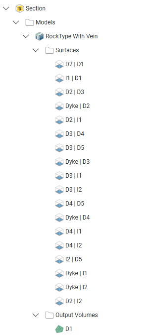
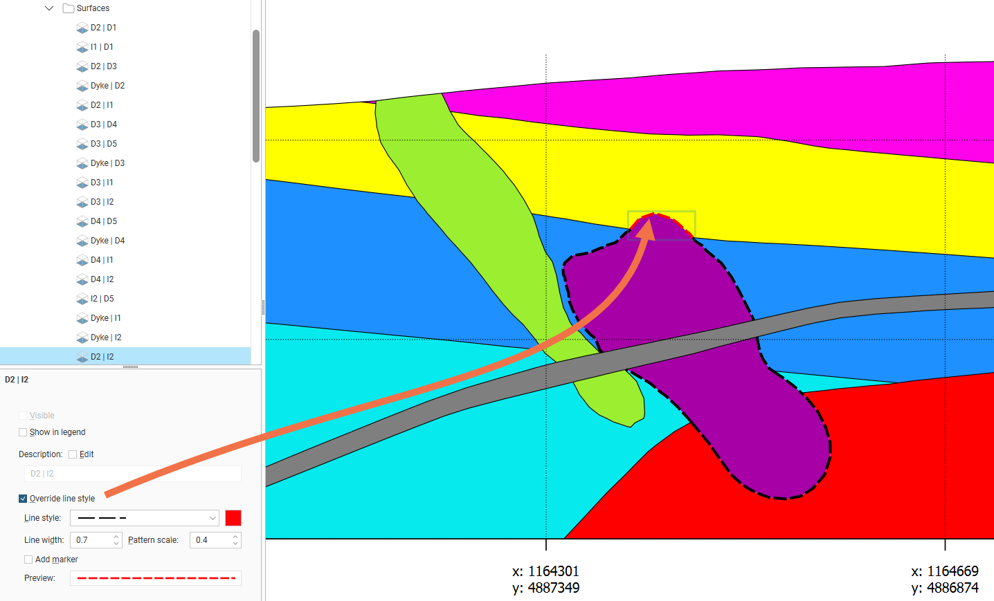
It can result in a large number of surfaces to work with, but does provide you more control over how these surfaces appear on the section layout. For example, here the outline of the purple I2 intrusion volume can be shown in different styles (as with the yellow D2 contact) or not at all (as with the grey Dyke contacts):
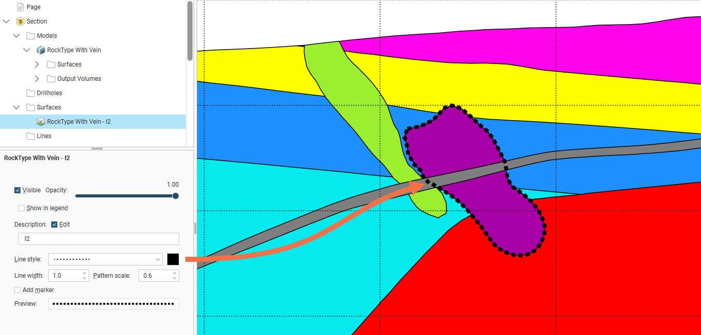
You could alternatively display a contact surface on a section layout as a surface evaluation, but you can have only one line style and you don’t have control over what parts of the surface are displayed. For example, you cannot hide the surface where it is intersected by the dyke:
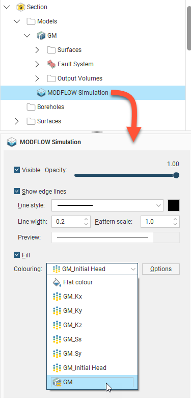
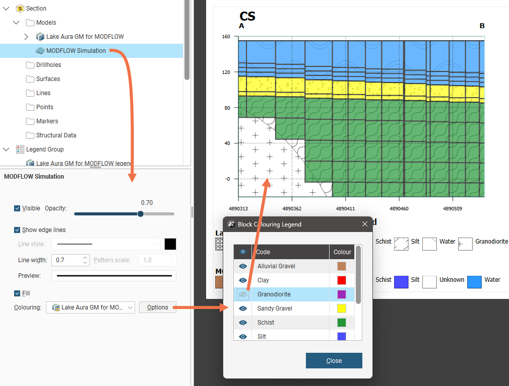
Flow models and block models appear in the Models folder as a single object. The Colouring option is used to display a flat colour or one of the model’s hydrological properties, with each of the hydrological categories available for the model being listed, or the geological model from which the model was gridded:
Click Options to change the colours used to display the model:
- For category evaluations, you can change what categories are visible and the colours used to display them, and hide categories so they are not displayed on the section layout.
- For numeric evaluations, you can filter values and use a different colourmap.
For example, here, a MODFLOW model is displayed using the Colouring from an evaluated geological model, and the block colouring legend window shows the category evaluation colour options:
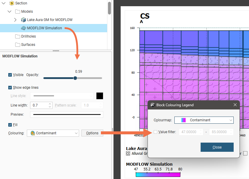
Here, the MODFLOW model is displayed using the Colouring from a hydrological evaluation, and the block colouring legend window shows the numeric evaluation colour options:
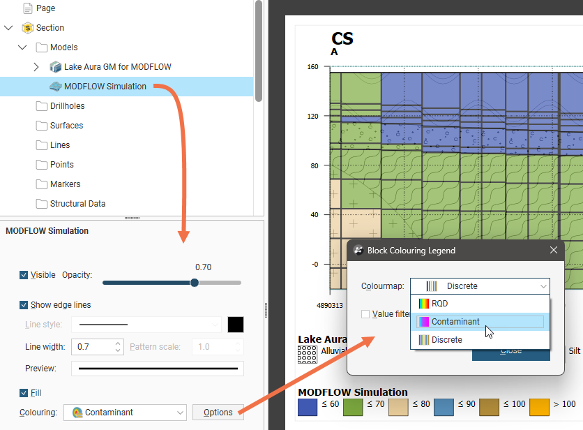
You can change the Colourmap used to display the model on the section and you can filter the values displayed.
If a block model or flow model is too big for the section layout, changing the section extents or the section layout extents will effectively “crop” the model and make it small enough to display on the section layout. There are two ways to do this:
- Change the section layout extents by clicking on Section in the layout tree, then clicking on the Extents tab. If Extents is set to Evaluation Extents, change it to Section Extents.
- Change the size of the section by double-clicking on it in the project tree and then editing its dimensions in the scene.