Creating Cross Sections
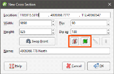
To create a cross section in the scene, add a model to the scene. Next, right-click on the Cross Sections and Contours folder and select New Cross Section. The New Cross Section window will appear, together with a section plane and controls in the scene that let you adjust the position of the section plane:
If the slicer is already in the scene when you select New Cross Section, the position of the slicer will be used to define the initial orientation of the section. This is an effective way of creating a section from the slicer: add the model to the scene, draw a slice and then create a cross section.
The front (F) and back (B) of the section plane is indicated in the scene. To swap the front and back, click the Swap Front button (![]() ).
).
Use the handles in the scene to position the section plane. The handles work in the same manner as the moving plane controls, as described in The Moving Plane.
Two buttons in the New Cross Section window let you create a cross section that is aligned north-to-south (![]() ) or east-to-west (
) or east-to-west (![]() ):
):
The other two buttons are active when the slicer is in the scene. Clicking the Set section to slicer button (![]() ) creates a cross section from the position of the slicer in the scene. When the Lock section to slicer button (
) creates a cross section from the position of the slicer in the scene. When the Lock section to slicer button (![]() ) is enabled, moving the position of the slicer will update the position of the cross section in the New Cross Section window.
) is enabled, moving the position of the slicer will update the position of the cross section in the New Cross Section window.
Once the section plane is positioned as required, click OK to create the new cross section, which will appear in the Cross Sections and Contours folder. Display it by clearing the scene, then adding the cross section to the scene.
Many objects in a project can be evaluated on cross sections, as described in Evaluations. Such objects include:
- Geological models
- Interpolants
- Distance functions
- Surfaces
- Design lines
- GIS lines
- Polylines
Objects evaluated on a cross section or fence section can be included when the section is exported.
Got a question? Visit the Seequent forums or Seequent support

