Alignment Serial Sections
An alignment serial section can be created using an alignment imported into the Designs folder, a polyline or a GIS line. When creating an alignment serial section from a polyline, you can use an existing polyline or draw a new one.
This topic describes the process of creating and working with an alignment serial section. It is divided into:
- Creating an Alignment Serial Section
- Displaying an Alignment Serial Section
- Exporting an Alignment Serial Section
Creating an Alignment Serial Section
To create an alignment serial section, right-click on the Cross Sections and Contours folder and select New Alignment Serial Section. The New Alignment Serial Section window will appear. Select whether you will use an existing line or create a new one.
Using an Existing Line
If you select an existing line, planes representing the base section and the offset sections will be added to the scene:
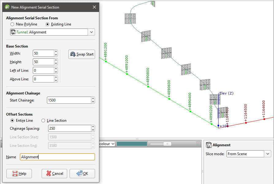
Once you have created an alignment serial section, you can change all settings except the line used.
The Base Section parameters determine the size of the sections and the Offset Section parameters determine how the sections are distributed along the selected line.
- Swap the start and end points of the selected line by clicking the Swap Start button.
- Generate sections along only part of the line by selecting Line Section, then changing the Start Chainage and End Chainage.
You can set a Start Chainage value that will be assigned to the first point of the line being used for the alignment.
All changes you make in the New Alignment Serial Section window will be displayed in the scene.
Click OK to create the section.
Using a New Polyline
If you have chosen to create a New Polyline, set the Base Section and the Offset Section parameters, then click OK. Drawing controls will appear in the scene and you can begin drawing, as described in Drawing in the Scene.
Once you have finished drawing the polyline, click the Save button (![]() ). The offset sections will be generated and will appear in the project tree. Double-click on the section in the project tree to edit its settings.
). The offset sections will be generated and will appear in the project tree. Double-click on the section in the project tree to edit its settings.
The Alignment Serial Section in the Project Tree
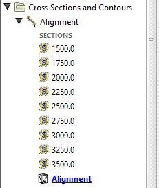
In the project tree, the alignment serial section includes the individual offset sections and the line used to create it:
Many objects in a project can be evaluated on serial sections, as described in Evaluations. Such objects include:
- Geological models
- Interpolants
- Distance functions
- Surfaces
- Design lines
- GIS lines
- Polylines
Displaying an Alignment Serial Section
Add the top-level section to the scene to view all the offset sections. You can also view individual offset sections.
If a master section layout has been created for an alignment serial section, dragging the master section layout into the scene displays all sections that use that layout.
Exporting an Alignment Serial Section
Alignment serial sections can be exported in the following formats:
- DXF Files (11/12 [AC1009]) (*.dxf)
- Drawing Files (2013/LT2013) (*.dwg)
- Bentley Drawing Files (v8) (*.dgn)
The DXF format exports a single file with a collection of DXF lines based on intersections between the selected evaluation and the section planes.
The offset sections that make up an alignment serial section can also be exported as a section layout. See Section Layouts for more information.
Got a question? Visit the Seequent forums or Seequent support