
Building Faulted Models
This topic describes how to use the fault system to create and organise faults:
- The Fault System
- Editing Faults
- Fault Interactions
- Activating the Fault System
- Copying the Surface Chronology to an Empty Fault Block
- Faulted Model Display Options
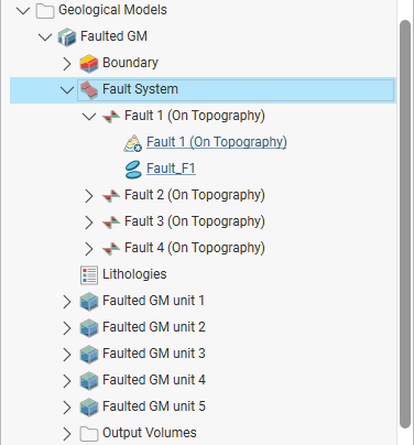
Each geological model is created with a Fault System object that is used to construct faults. Once the faults are active in the geological model, the geological model will be divided into separate fault blocks, which will appear in the project tree as part of the model. Here, the geological model has been divided into five fault blocks:

Each fault block has its own Surface Chronology, which can be modified without affecting other fault blocks in the geological model. There is no top-level Surface Chronology for the geological model once the Fault System has been activated. This means that lithology layers can be constructed for a faulted model in two ways:
- Define the Surface Chronology before enabling the Fault System. All surfaces defined for the unfaulted model will automatically be copied to each fault block. Some surfaces defined for the model as a whole will not occur in every fault block, which can be corrected by working with the surfaces in each fault block.
- Enable the Fault System before any surfaces are defined in the unfaulted model, then define the Surface Chronology for each fault block. An aid to working with a faulted model in this way is the ability to copy contact surfaces from one faulted block to another. See Copying the Surface Chronology to an Empty Fault Block below.
Which approach is best depends on the model being built. You may already know where the faults are and choose to define them and subdivide the geological model before defining any lithology layers. On the other hand, sometimes it is not apparent where the faults are until the layers have been built, in which case you can add the new fault, activate it in the model, then work with the surfaces in each fault block.
The Fault System
When a geological model is first created, the Fault System object is empty. To create faults, right-click on the Fault System object and select from the options available. Many of these options are similar to those for creating lateral extents. For more information, see the follow subtopics in the Modifying a Geological Model’s Boundary topic:
- Extent From a Polyline
- Extent From GIS Vector Data
- Extent From Points
- Extent From Structural Data
- Extent From a Surface
Faults created from polylines and GIS vector data can be created as vertical walls or surfaces. Faults created as surfaces can be modified by adding further data, as described in Editing Faults below.
Creating a fault from the base lithology or other contacts is similar to creating contact surfaces. See Creating Deposits/Erosions From the Base Lithology and Deposits and Erosions From Other Lithology Contacts for more information.
Faults (![]() ) will appear in the project tree as part of the Fault System object (
) will appear in the project tree as part of the Fault System object (![]() ) and can be expanded to show how they were created. Here, Fault 1 was created from a GIS line draped on the topography (
) and can be expanded to show how they were created. Here, Fault 1 was created from a GIS line draped on the topography (![]() ) and structural data (
) and structural data (![]() ):
):
Once faults have been created, you can modify them as described in Editing Faults.
Editing Faults
Once a fault has been defined, you can refine it in several ways:
- Add other data. This option is available for faults created as surfaces, but not for those created as vertical walls. Right-click on the surface to see the options available, which will depend on how the surface was created.
- Edit the surface with a polyline. Right-click on the surface in the project tree and select either Edit > With Polyline. See Editing Surfaces With Polylines for more information.
- Edit the surface using structural data. Right-click on the surface and select Edit > With Structural Data. See Editing Surfaces With Structural Data for more information.
You can also:
- Change surfacing options. See Surfacing Options for Faults.
- Change the data objects used in the fault. See Changing Fault Inputs.
- Apply a global trend to a fault. See Applying a Trend to a Fault.
Surfacing Options for Faults
Settings such as surface resolution, boundary filtering and snapping can be set for the model as a whole but these can also be set on a surface-by-surface basis.
See the Creating and Editing a Geological Model topic for information on these settings for the overall geological model.
To change surfacing options for a fault, double-click on the fault in the project tree, then click on the Surfacing tab.
The settings in the Surfacing tab will be disabled if the fault inputs have been replaced with a mesh.
Boundary Filtering
When data objects are added to a fault, there are two ways to handle the data that lies outside the fault boundary:
- Filter the data. The fault is only influenced by the data that falls inside the fault boundary.
- Leave the data unfiltered. The fault is influenced by the data both inside and outside the fault boundary.
The Boundary filter setting determines how data used to define the fault is filtered:
- Inherit from GM. The setting for the geological model as a whole is used. This is the default setting.
- Off. Data is not filtered.
- All data. All data is filtered.
- Drilling only. Only drilling data and data objects derived from drilling data are filtered.
- Custom. Only the data objects specified in the Inputs tab are filtered.
Snapping to Data
There is a Snap to data setting for a geological model as a whole that is set in the Geological Model > General tab (see Creating and Editing a Geological Model). Snap to data can also be set on a surface-by-surface basis by double-clicking on the surface in the project tree and then clicking on the Surfacing tab.
For faults, the options are:
- Inherit from GM. The setting for the geological model as a whole is used. This is the default setting.
- Off. The fault surface does not snap to the data used to create it.
- All data. The fault surface snaps to all data within the Maximum snap distance, which includes drilling data and any data added to the fault.
- Drilling only. The fault surface snaps to drilling data and data objects derived from drilling data within the Maximum snap distance but not to other data used to modify the fault. For example, the fault surface will honour points data derived from drilling data, but not points data imported into the Points folder.
- Custom. The fault surface snaps to the data objects indicated in the Inputs tab.
Take care in enabling snapping and in selecting what data the surface will snap to, as the more data you include, e.g. by setting a large Maximum snap distance or selecting All data for Snap to data, the greater the possibility that errors in the data or assumptions inherent in interpretations (e.g. polylines) will cause distortions in the meshes. If you do enable snapping, it is best to snap only to drilling data. See Honouring Surface Contacts in the Modifying Surfaces topic for more information on these settings.
If you need the fault surface to honour drilling data but treat other data objects as interpretations, select Drilling only. To honour some data objects while treating others as interpretations, select Custom, then click on the Inputs tab to enable snapping for individual objects.
Changing Fault Inputs
For faults, the Inputs tab shows all the data objects used to create the fault and whether the Snap and Boundary filter options are enabled for each object used to define the fault. If an input has any query filters defined, you can select one in this window.

You can also replace the fault’s inputs with a single mesh or add more data to the fault.
Replacing Fault Inputs With a Single Mesh
To replace the fault inputs with a single mesh, click on the Mesh option, then select from the meshes available in the project.
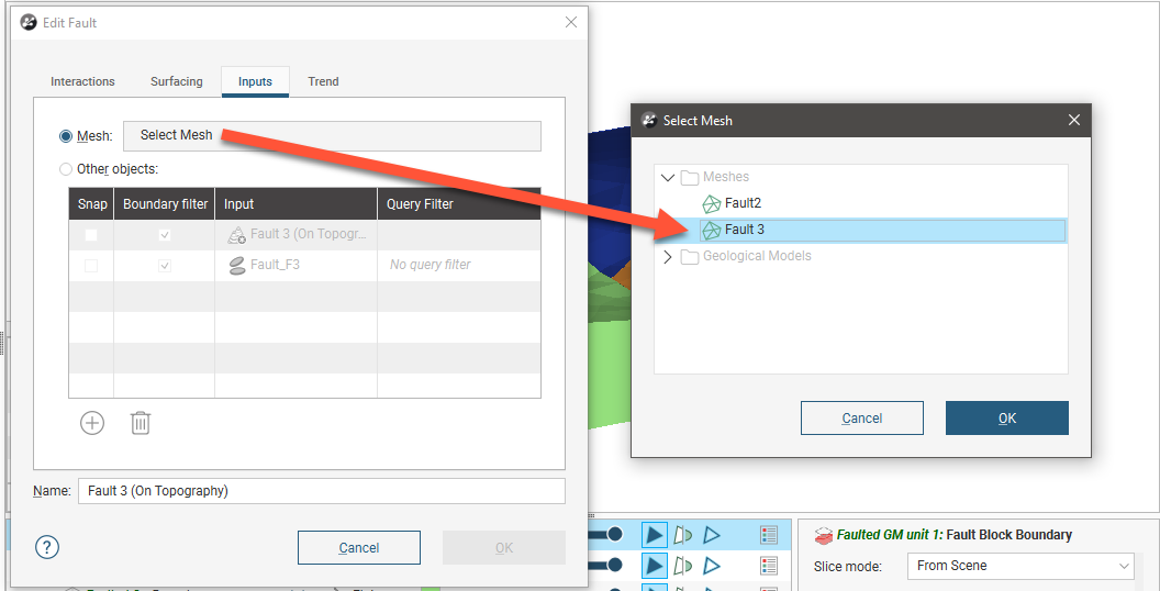
When you select a single mesh to define the fault, all other inputs listed in the Inputs tab will be removed from the fault. This can result in objects being deleted from the project. For example, if the fault has been edited using a polyline, the polyline will be deleted when the inputs are replaced with the mesh. If you wish to retain such inputs, be sure to share the object before changing the inputs. See Sharing Objects for more information.
The snap and boundary filtering controls in the Surfacing tab will be disabled as the settings from the geological model will be used. The settings in the Trend tab will also be disabled as it is not possible to set a trend for a fault defined from a mesh.
Adding Data to the Fault
To add more data to the fault, click on the Select Objects button, then select from the suitable objects available in the project.
Snap Settings for Individual Inputs
The Snap setting determines whether or not the faults surface honours a particular data object. Often, surfaces should honour drilling data and treat data objects such as polylines and GIS data as interpretations, as discussed in Honouring Surface Contacts. To change snap settings for a fault, click on the Surfacing tab and set Snap to data to Custom. You will then be able to change Snap settings in the Inputs tab.
Boundary Filtering Settings for Individual Inputs
When data objects are added to a fault, there are two ways to handle the data that lies outside the fault boundary:
- Filter the data. The fault is only influenced by the data that falls inside the fault boundary.
- Leave the data unfiltered. The fault is influenced by the data both inside and outside the fault boundary.
To change the Boundary filter settings for each object used to define a fault, click on the Surfacing tab and set Boundary filter to Custom. You will then be able to change Boundary filter settings in the Inputs tab.
Applying a Trend to a Fault
To apply a trend to a fault, either:
- Double-click on the fault in the project tree, then click on the Trend tab.
- Right-click on the fault in the project tree and select Adjust Surface. This opens the Edit Fault window with the Trend tab displayed.
See Global Trends in the Trends and Anisotropy topic for information on using the controls in this tab.
The settings in the Trend tab will be disabled if the fault inputs have been replaced with a mesh.
Fault Interactions
Once all the faults required have been created, you can start defining the interactions between the faults by double-clicking on the Fault System object. The Geological Model will be opened with the Fault System tab displayed:
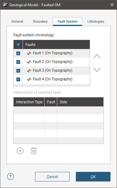
To add an interaction, click on a fault, then click the Add button. Select the Interaction Type and set how the faults interact:

Once you have defined each fault interaction, click OK to generate the fault system. Add the Fault System object to the scene to check that the faults interact correctly.
You can also edit fault interactions by double-clicking on individual faults. The Edit Fault window will open, which shows only the interactions for the selected fault:
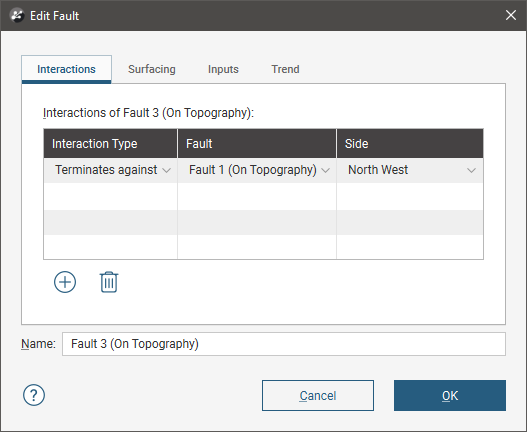
Faults are not active in the geological model until the box is ticked for each fault in the Fault System window, as described in Editing Faults. This means you can check the fault system without regenerating the geological model.
Activating the Fault System
Activating the fault system divides the geological model into fault blocks, which can result in considerable processing time for complex models. It is important, therefore, to define fault interactions before enabling the fault system, otherwise a large number of fault blocks could be generated that significantly increase processing time. See Fault Interactions above.
To activate the fault system in the geological model, double-click on the Fault System object once again and tick the box for each fault. The model will be divided into separate fault blocks that can be worked with in a similar manner to the geological model as a whole.
Copying the Surface Chronology to an Empty Fault Block
If you have defined the surface chronology for one fault block, you can copy it to other empty fault blocks. To do this, right-click on the Surface Chronology for which you have defined surfaces and select Copy Chronology To.
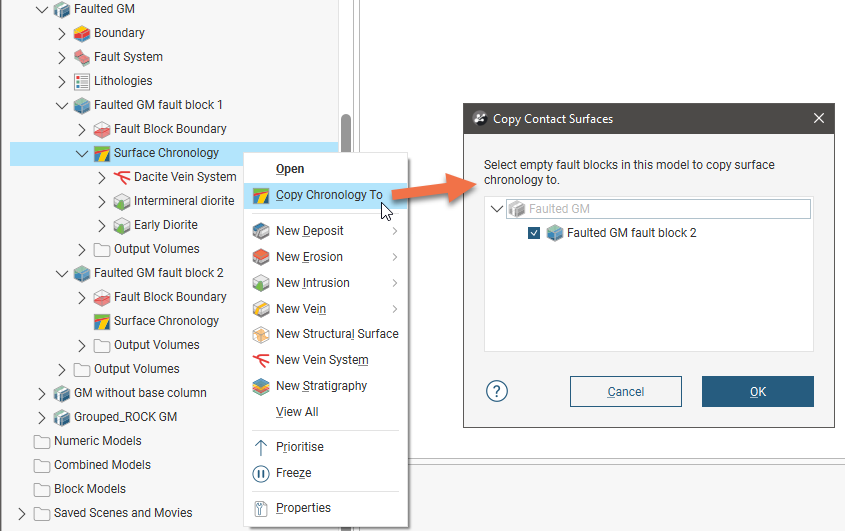
In the window that appears, select the fault blocks you want to copy contact surfaces to and click OK. The surfaces will be copied and you can modify them without affecting the surfaces in the other fault blocks.
Note that a fault block’s surface chronology must be empty before you copy surfaces from another fault block to it.
Faulted Model Display Options
Drag the model into the scene or right-click on it and select View Object; these options add the model to the shape list as a single object and you can change the visibility of each lithology by clicking the Edit Colours button. You can also add the model to the scene as a series of output volumes by right-clicking on the model and selecting View Output Volumes.
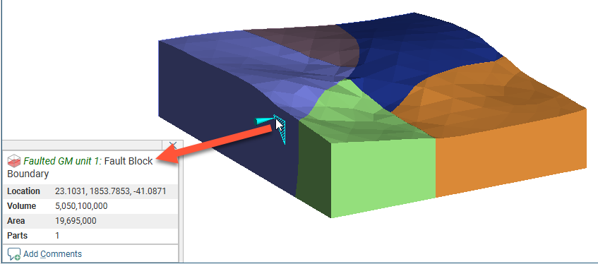
Another display option lets you view the individual fault blocks without displaying the lithology layers. Right-click on the model and select View Fault Block Boundaries.
To work with a specific fault block, click on it in the scene. The window that appears displays the name of the selected fault block:
You can also view the output volumes for each individual fault block by right-clicking on the fault block in the project tree and selecting View Output Volumes.
Got a question? Visit the Seequent forums or Seequent support
© 2023 Seequent, The Bentley Subsurface Company