
Creating and Editing a Geological Model
When you first create a geological model, you need to set:
- The lithology data column that will be the basis for the geological model, if you are using lithology data, and whether or not to apply a filter
- General surfacing options, such as the surface resolution and whether or not to use adaptive isosurfacing or single-pass isosurfacing
- The model’s extents
All of these settings can be changed once a model is created.
This topic describes the process of creating a new geological model and editing its basic settings, those relating to the base lithology column, surface resolution and the model boundary. It is divided into:
- Selecting the Base Lithology
- Surface Resolution for a Geological Model
- Setting the Geological Model’s Extents
- Changing Default Boundary Filtering
- Changing Default Snapping Behaviour
- Changing Output Volume Generation
- Building the Geological Model
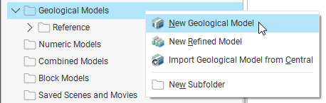
To create a new geological model, right-click on the Geological Models folder and select New Geological Model:
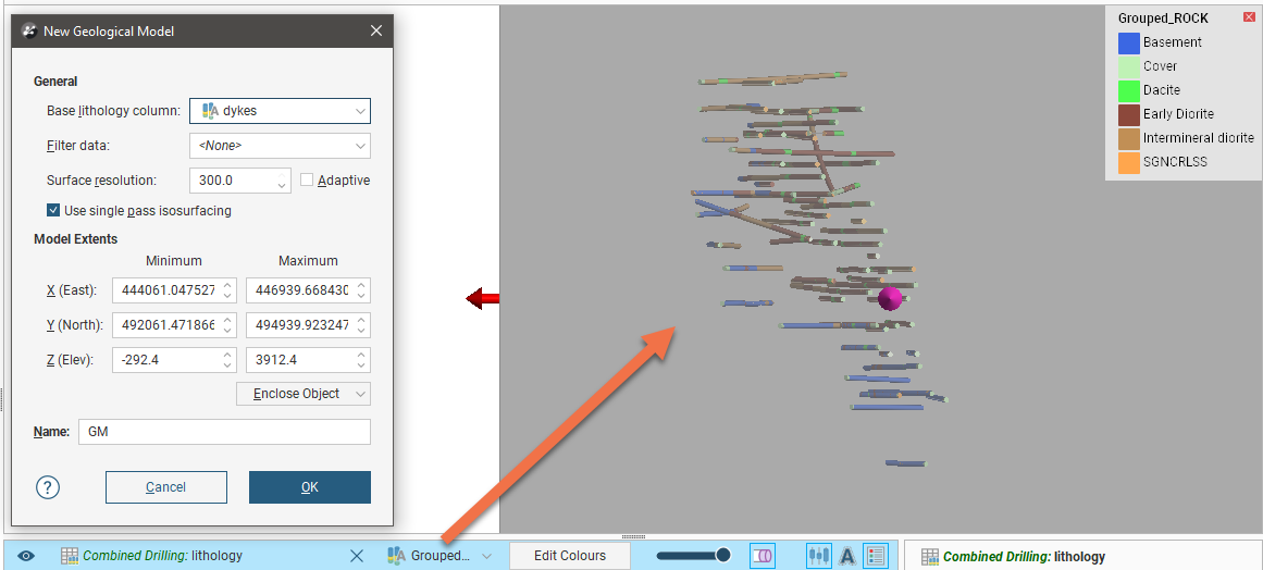
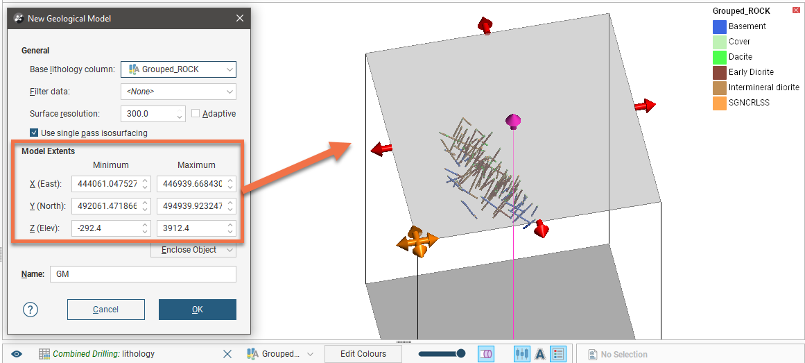
In the rest of this topic, we will use as an example creating a geological model from the Grouped_ROCK column in a combined drilling data set. Here that column has been added to the scene and viewed from above in order to help in setting the model’s extents:
Once you have set the base lithology, the surfacing options and the model’s extents, enter a name for the model and click OK to create the new model. The new geological model will be created and added to the Geological Models folder.
See the Geological Models topic for a discussion of how the different parts of the geological model are organised.
Selecting the Base Lithology
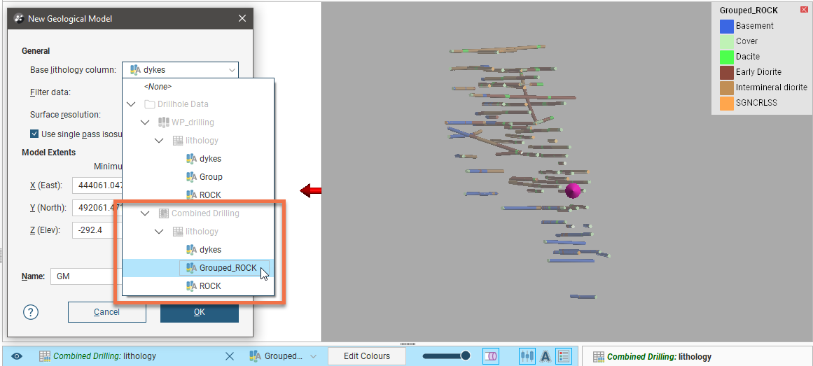
First select the drilling data column that will be used as the basis of a model from the Base lithology column list. If you do not wish to use lithology data as the basis for the model, select <None>. This may be the case if, for example, you want to build a model from points data or from an imported map. If you select <None>, you will need to manually define the lithologies that will be modelled.
Leapfrog Geo automatically selects the first lithology column available in the project, so make sure you select the column you wish to use. Here, the model will be based on the Grouped_ROCK column in the Combined Drilling data set:
Once the model has been created, you can change the Base lithology column, but it is not a straightforward process, especially once you have started building the model’s surfaces. See Changing a Geological Model’s Base Lithology Column for more information.
You can also filter the drilling data used to build the geological model using any query filters that have been defined for the selected drilling data set. To do so, select the required query filter from the Filter data list. Once the model has been created, you can remove the filter or select a different one.
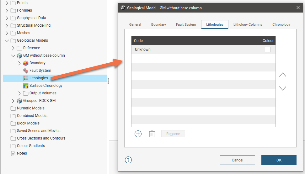
The lithology codes from the Base lithology column are used as the geological model’s lithology codes, which you will be able to see once the model has been created. For example, here we can see in the Geological Model window the lithologies used in a newly-created geological model:
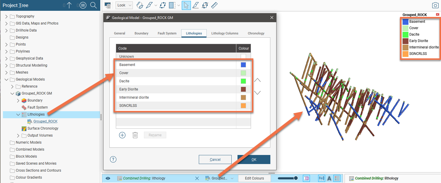
The lithology column used as the base lithology column is displayed in the scene, along with its legend. Note that the model’s Lithologies tab shows the same lithologies as the base lithology column, along with the lithology “Unknown”.
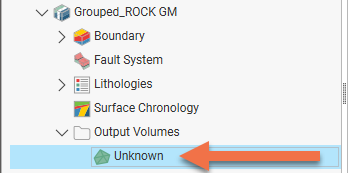
The lithology code Unknown is automatically defined for all geological models. Unknown is used to label lithologies that cannot be assigned to known lithologies, i.e. those derived from lithology data or manually added to the list. When a geological model is first created and no contact surfaces have been defined, the output volume’s lithology cannot be determined and so the Unknown lithology code is used for the output volume. That is the case here, with a new geological model in which no contact surfaces have been defined:
When you create a geological model without assigning a Base lithology column, the only code in the Lithologies list will be Unknown:
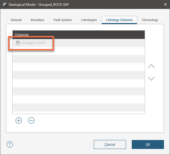
The Geological Model window also has a Lithology Columns tab. This is used to add more lithology codes to the Lithologies list. When a model is created using a Base lithology column, that column will be listed in the Lithology Columns tab, as shown here:
See the Geological Model Lithologies topic to learn more about how the lithology codes in the Lithologies tab are derived, how to use the Lithology Columns tab to add more codes to the list and how the use a background lithology as an alternative to “Unknown”.
Surface Resolution for a Geological Model
When you create a geological model, the Surface resolution value and Adaptive and Use single pass isosurfacing options set in the New Geological Model window are used for the model as a whole:
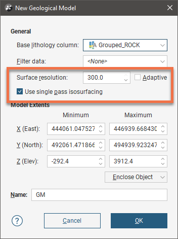
The Surface resolution value Leapfrog Geo automatically uses as the default is based on the data available in the project. For more information about these settings, see Surface Resolution in Leapfrog Geo.
When surfaces and boundaries are created as part of the model-building process, their resolution is inherited from the geological model:
- For contact surface other than intrusion contact surfaces and all boundary surfaces, the resolution is the same as the geological model.
- For intrusion contact surfaces, the resolution is half that set for the geological model.
In many cases, you can also set these surfacing options on a surface-by-surface basis, which is useful if you want to build a detailed model of some lithologies without increasing processing time for other volumes. To do this, double-click on the surface in the project tree, then click on the Surfacing tab. Here a vein contact surface has been created with the default setting of inheriting the geological model’s resolution settings:
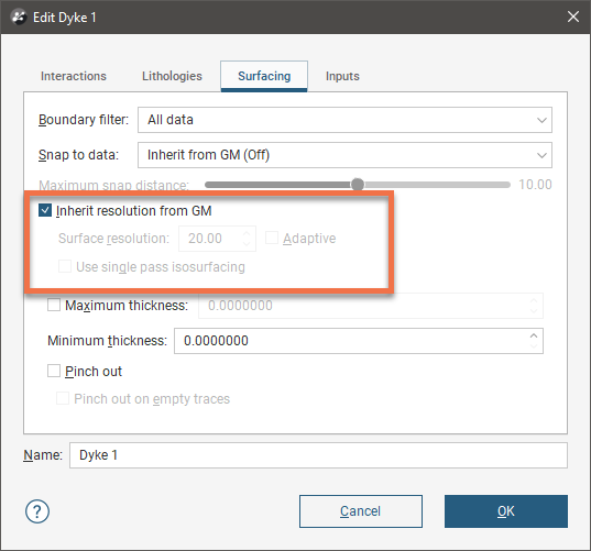
To use different settings, disable the Inherit resolution from GM option, then change the required settings.
The resolution of intrusion contact surfaces is also affected by the point generation parameters. See Intrusion Point Generation Parameters for more information.
Setting the Geological Model’s Extents
A geological model is initially created with a basic rectangular set of extents aligned with the south/north and east/west axes.
When you are creating a new geological model, controls are shown in the scene that will help you in setting the model’s extents:
You can define the model’s extents in three ways:
- Use the controls in the scene. The orange handle adjusts the location of the corner of the extents box, the red handles adjust the width and depth and the pink handles adjust the height.
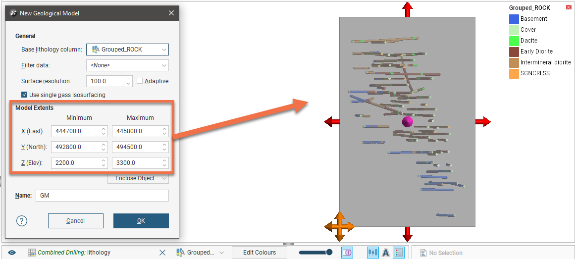
- Enter the coordinates in the New Geological Model window.
- Select Enclose Object and choose from the list of objects in the project.
If the model is based on drilling data, select the lithology segments from the Enclose Object list, as shown here:
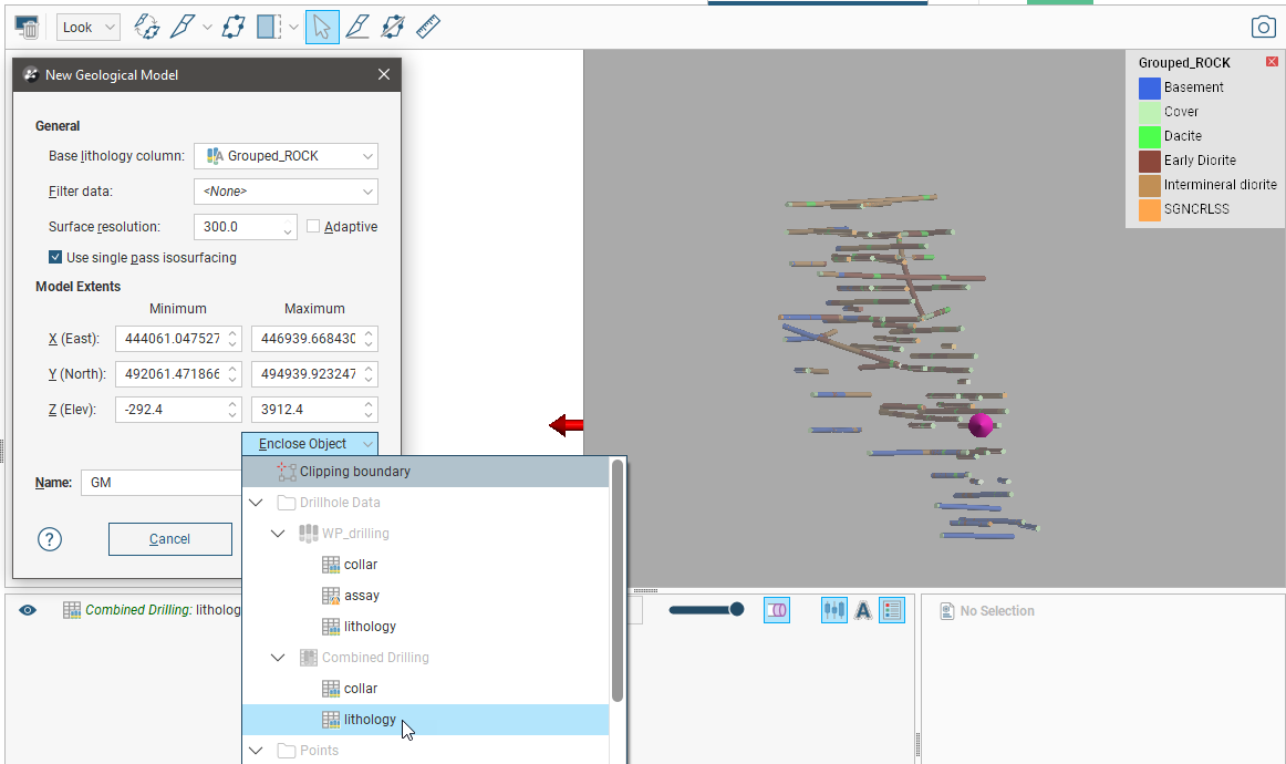
The in-scene controls will be updated to show the extents of the selected object:
See Object Extents in the Boundaries in Leapfrog Geo Projects topic for more information.
Once a geological model’s rectangular extents have been defined, you can further the modify the boundary to better reflect the ground surface and boundaries of the area of interest. Furthermore, extents do not need to be strictly vertical surfaces. For example, surfaces from elsewhere in the project can be used as custom extents for a geological model. See Modifying a Geological Model’s Boundary for more information.
Changing Default Boundary Filtering
When data objects are added to a surface in the geological model, there are two ways to handle the data that lies outside the surface’s boundary:
- Filter the data. The surface is only influenced by the data that falls inside the surface’s boundary.
- Leave the data unfiltered. The surface is influenced by the data both inside and outside the surface’s boundary.
By default, geological models are created with boundary filtering on for all data used to build the model. This default value can be changed once the model has been created and later, as you build model surfaces, you can also set boundary filtering on a surface-by-surface basis.
To change the default boundary filtering option for a geological model as a whole, double-click on the model in the project tree. The default Boundary filter setting is in the General tab:
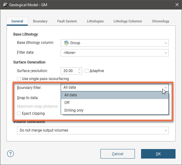
Options are:
- Off. Data is not filtered.
- All data. All data is filtered.
- Drilling only. Only drilling data and data objects derived from drilling data are filtered.
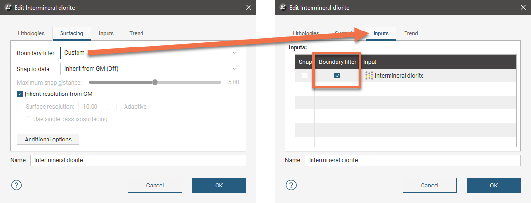
To change boundary filtering for individual surfaces, double-click on the surface in the project tree, then click on the Surfacing tab. Options For Boundary filtering are:
- Inherit from GM. The setting for the geological model as a whole is used. This is the default setting.
- Off. Data is not filtered.
- All data. All data is filtered.
- Drilling only. Only drilling data and data objects derived from drilling data are filtered.
- Custom. Only the data objects specified in the Inputs tab are filtered.
When you choose Custom for individual surfaces, you can select which data to filter from the surface’s Inputs tab.
Changing Default Snapping Behaviour
Often, surfaces should honour drilling data and treat data objects such as polylines and GIS data as interpretations, as discussed in Honouring Surface Contacts in the Modifying Surfaces topic.
By default, geological models are created with snapping off for all data used to build the model. This default value can be changed once the model has been created and later, as you build model surfaces, you can also set snapping behaviour on a surface-by-surface basis.
To change the default snapping behaviour for a geological model as a whole, double-click on the model in the project tree. The default Snap to data setting is in the General tab:
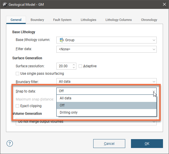
Options are:
- Off. Surfaces do not snap to the data used to create them.
- All data. Surfaces snap to all data within the Maximum snap distance, which includes drilling data and any data added to the surfaces.
- Drilling only. Surfaces snap to drilling data and data objects derived from drilling data within the Maximum snap distance but not to other data used to modify the surfaces.
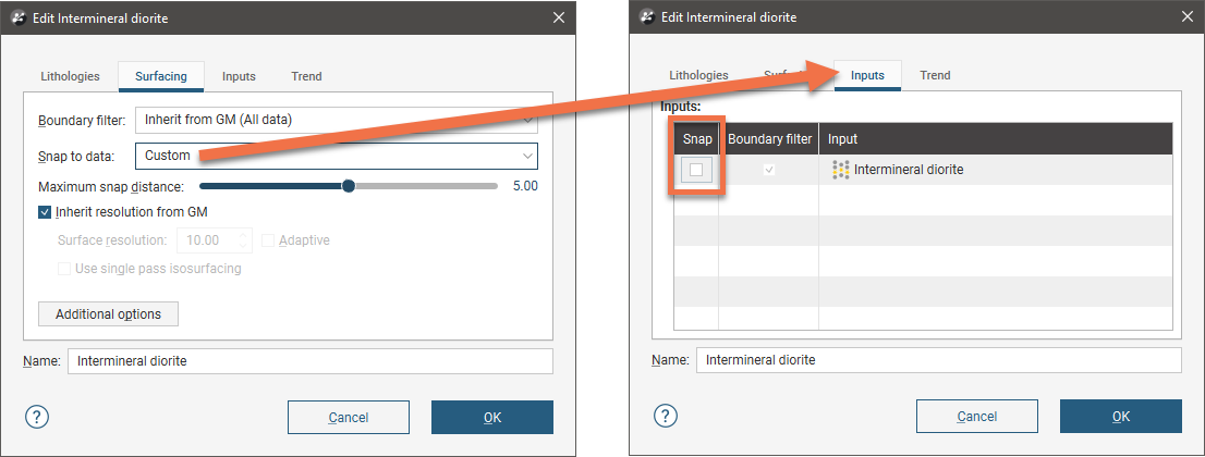
To change snapping behaviour for individual surfaces, double-click on the surface in the project tree, then click on the Surfacing tab. Options for Snap to data are:
- Inherit from GM. The setting for the geological model as a whole is used. This is the default setting.
- Off. Surfaces do not snap to the data used to create them.
- All data. Surfaces snap to all data within the Maximum snap distance, which includes drilling data and any data added to the surfaces.
- Drilling only. Surfaces snap to drilling data and data objects derived from drilling data within the Maximum snap distance but not to other data used to modify the surfaces.
- Custom. Surfaces snap to the data objects indicated in the Inputs tab for each surface.
When you choose Custom for individual surfaces, you can select which data to filter from the surface’s Inputs tab.
Take care in enabling snapping and in selecting what data the surface will snap to, as the more data you include, e.g. by setting a large Maximum snap distance or selecting All data for Snap to data, the greater the possibility that errors in the data or assumptions inherent in interpretations (e.g. polylines) will cause distortions in the meshes. If you do enable snapping, it is best to snap only to drilling data. See Honouring Surface Contacts in the Modifying Surfaces topic for more information on these settings.
If you need a surface to honour drilling data but treat other data objects as interpretations, select Drilling only. To honour some data objects while treating others as interpretations, select Custom, then click on the Inputs tab to enable snapping for individual objects.
Changing Output Volume Generation
The Volume Generation setting determines whether or not output volumes of the same lithology are merged when the volumes are exported.
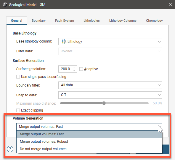
If this is set to Merge output volumes: Fast or Merge output volumes: Robust, internal walls and surface seams will be removed from volumes of the same lithology. The difference between Fast and Robust is the algorithm used:
- Fast removes back-to-back triangles before generating output volumes.
- Robust uses the volume cutter, which tracks where the triangles originated and is, therefore, a slow option for building output volumes.
Either option is suitable when you are using output volumes as extents for other models.
If there are issues with surfaces exported to other packages and the volumes have been generated using the Do not merge output volumes setting, try the Fast setting. If there are still issues, try the Robust setting.
Building the Geological Model
This topic has covered the basics of setting up a geological model. For more information on the model building process see:
Got a question? Visit the Seequent forums or Seequent support
© 2023 Seequent, The Bentley Subsurface Company