
Fully Sub-blocked Models
With fully sub-blocked models, blocks are fully sub-divided when they contain a triggering boundary. This can create many sub-blocks and so processing a fully sub-blocked model can be slower than processing an octree-sub-blocked model. In contrast to octree sub-blocked models, however, fully sub-blocked models support block subdivisions using numbers other than power-of-two numbers. Fully sub-blocked models do not support variable height sub-blocks.
Fully sub-blocked models can be exported in CSV and Datamine formats.
This topic describes:
- Creating a Fully Sub-blocked Model
- Selecting Triggers and Evaluations
- Selecting Meshes for Calculating Proportions
- Exporting Fully Sub-blocked Models
Creating a Fully Sub-blocked Model
To create a new fully sub-blocked model, right-click on the Block Models folder and select New Block Model. In the window that appears, select the Fully Sub-blocked Model option.
The New Fully Sub-blocked Model window will appear, together with a set of controls that will help you set the size, location and orientation of the model in the scene:
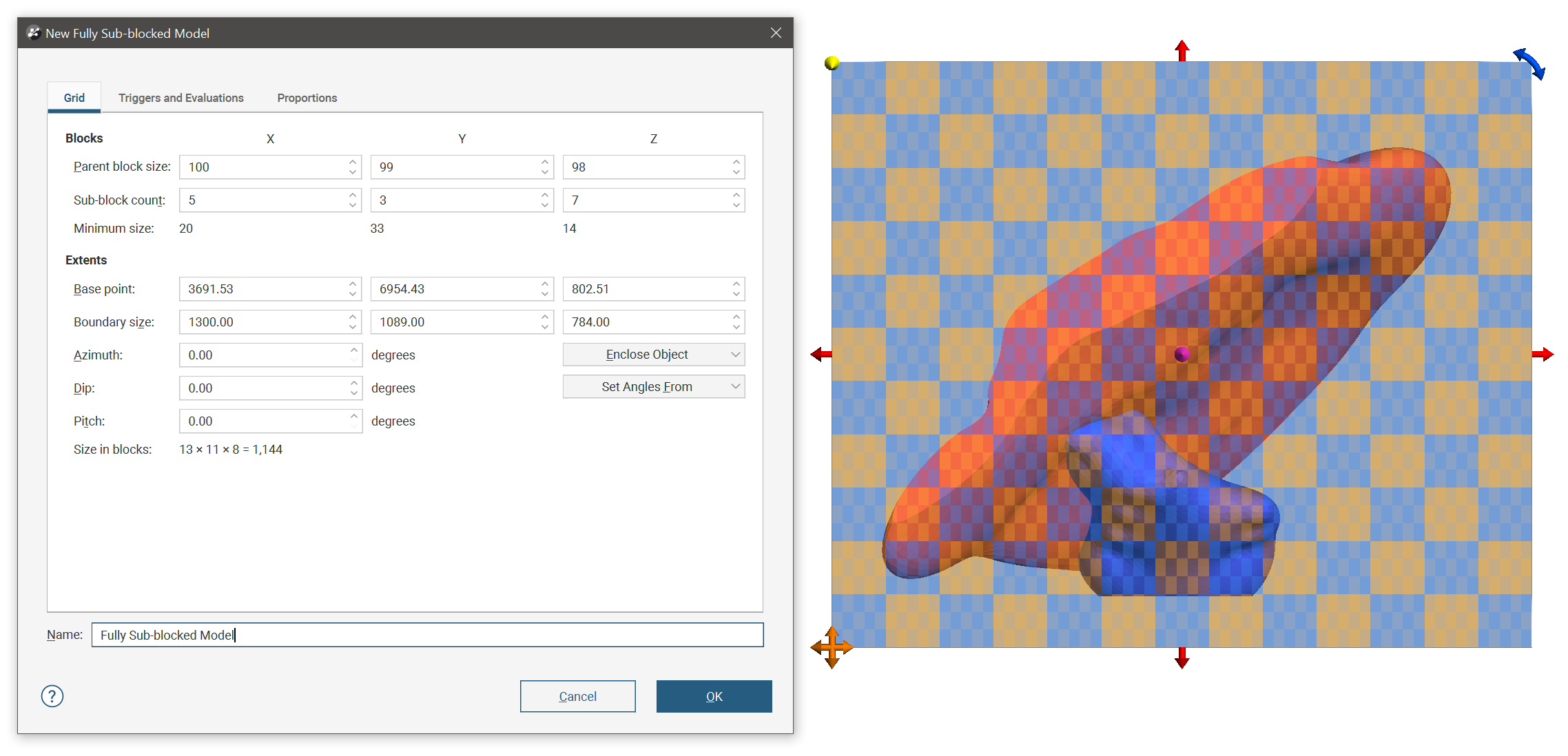
The block model is defined from its Base point, and the reference centroid is the Base point plus one half the Block size. Block models extents always include complete blocks, even when sub-blocking, and when changes are made to the Block size parameter, the model’s extents will be enlarged to fit the Block size.
It is a good idea to set the fully sub-bocked model’s extents from another object in the project, selecting the required object from the Enclose Object list.
The Dip and Azimuth set the rotation of the model. If you know the values you wish to use, enter them in the New Fully Sub-blocked Model window. You can also:
- Use the controls in the scene to set the orientation. The yellow handle adjusts the Dip and the blue handle adjusts the Azimuth.
- Use either the slicer or the moving plane to set the orientation. To do this, add the slicer or the moving plane to the scene and adjust the orientation. Then select the object to use from the Set Angles From list.
If you have set the extents from another object and then rotated the model, you will need to reset the extents by selecting the object again from the Enclose Object list.
The cross-hatched pattern displayed in the scene is useful in understanding how the parent blocks will be divided into sub-blocks. These properties can be changed by adjusting the Parent blocks and Sub-blocks settings. The Sub-block count is the number of divisions a parent block will be divided into in a particular direction when it intersects a trigger.
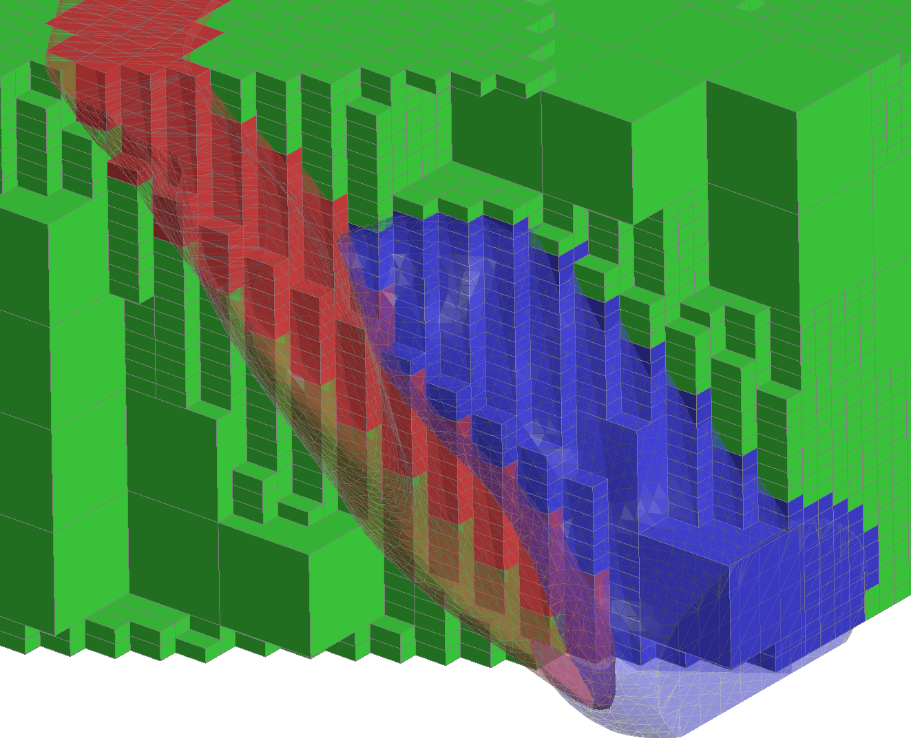
Here the block size is 100x99x98 and the sub-block count is 5 x 3 x 7, so blocks will either be full sized 100x99x98 blocks or 20x33x14 sub-blocks. Note the change from full to sub-block sizes as the sub-blocking is triggered on the geological model surfaces, two of which are shown (in red and blue):
Once you have set triggers, evaluations and proportions, enter a Name for the fully sub-blocked model and click OK. The model will appear under the Block Models folder. You can make changes to it by double-clicking on it.
Selecting Triggers and Evaluations
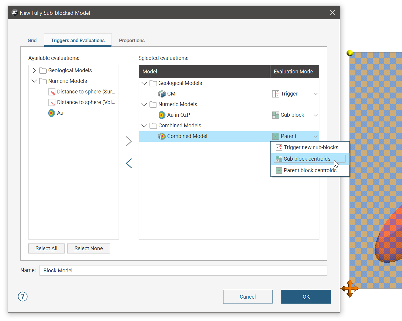
Click on the Triggers and Evaluations tab to select from the volumes available in the project.
Triggers can be:
- Geological model volumes
- Combined model volumes
Meshes and interpolants cannot be used to trigger fully sub-blocked model sub-blocking.
Evaluations can be:
- Geological model volumes
- Combined model volumes
- Grouped meshes
- Interpolants
- Distance functions
All suitable objects in the project will be displayed in the Available evaluations list.
Move the models you wish to use into the Selected evaluations list, then select the Eval. Mode. You can select from Existing sub-block centroids or Parent block centroids. Models that can trigger sub-blocking will also have the option to Trigger new sub-blocks. These selected options are abbreviated in the edit window as Sub-block, Parent, and Trigger respectively.
Selecting Meshes for Calculating Proportions
Proportions is only available if you have the Leapfrog Edge extension.
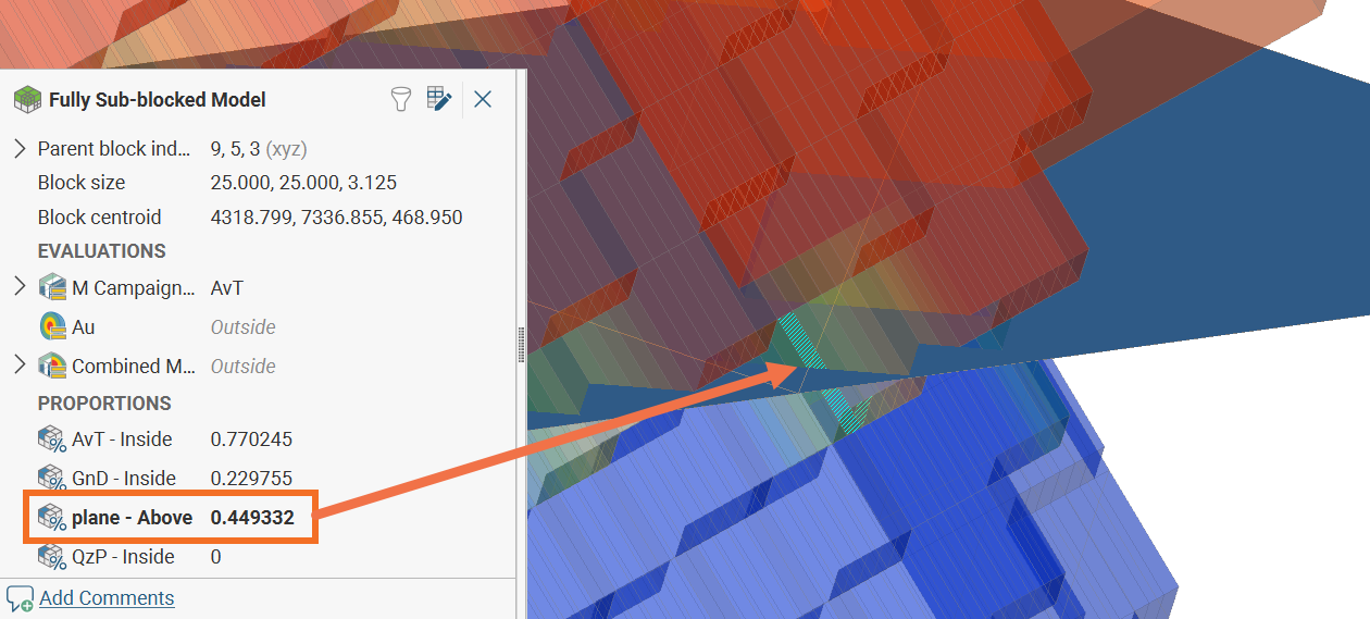
Click the Proportions tab and select meshes from the list of Available meshes, moving them to the Selected meshes list. The Proportions of Block column specifies the region of interest relative to the selected mesh. Closed meshes have options of Inside and Outside, and open meshes have the options of Above and Below.
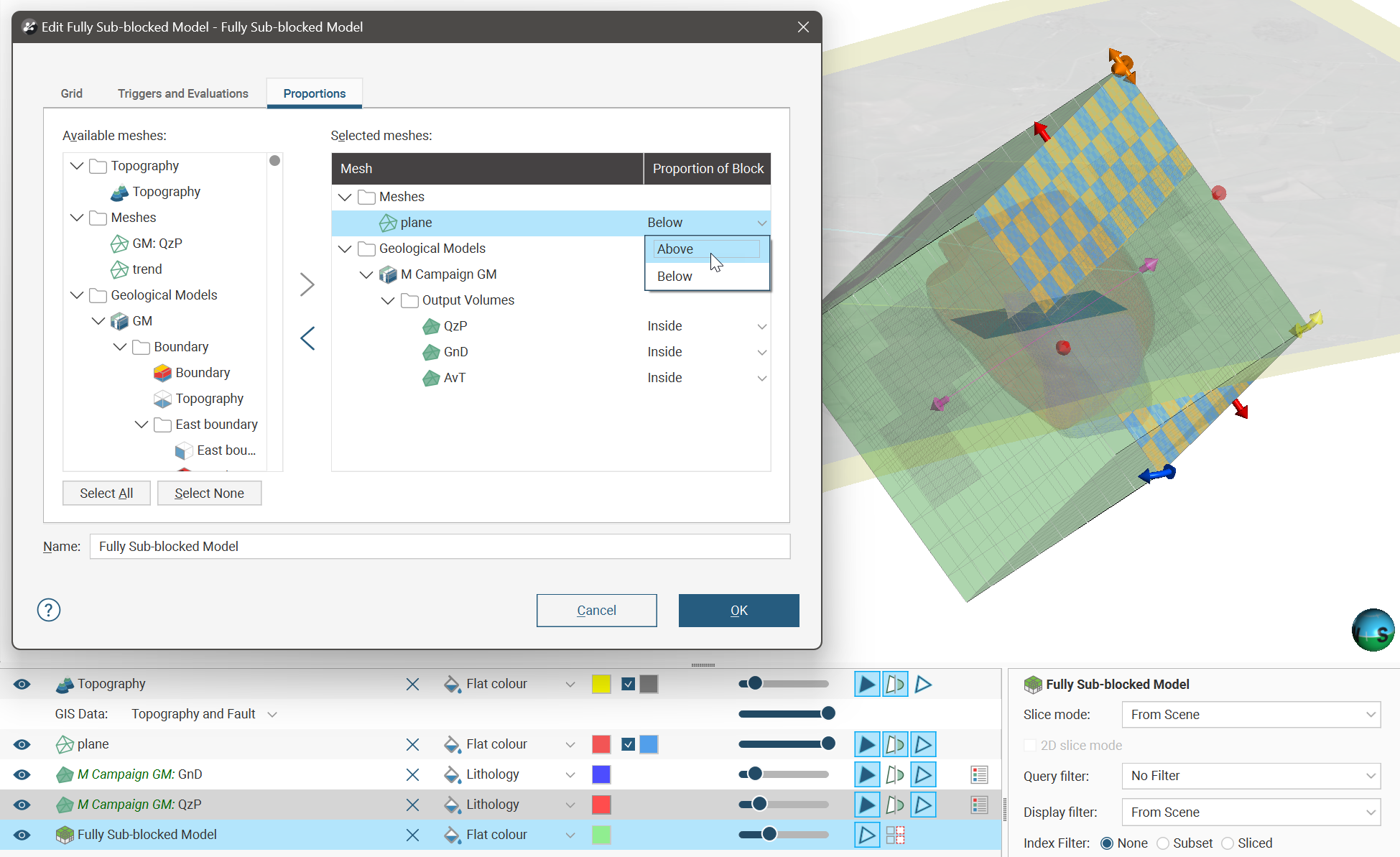
Each block will have a proportion calculated according to the ratio of each block relative to the Proportions of Block options for each surface. In the following example, a little less than half of the selected block is above the mesh called ‘plane’, and the exact proportion has been calculated as 0.449332. The same block has a proportion of 0.229755, or just under 23%, inside a mesh called ‘GnD’ (not shown).
When determining the proportion of a block above or below a selected mesh, if any part of a block falls outside a vertical projection of the outer edges of the surface, the proportion will be set to the special value Outside. Only blocks that are entirely within the vertical projection of the surface edge will be assigned a proportion value.
Non-manifold and self-intersecting meshes cannot be used for calculating proportions. Additionally, it is not possible to calculate the proportions above or below an open surface if there are overhangs and overlaps in the mesh.
Exporting Fully Sub-blocked Models
Fully sub-blocked models can be exported in CSV and Datamine formats. See: