Multiple Deviation Drilling Planner
The multiple deviation drilling planner caters for two typical drilling scenarios:
- Reflecting the expected lift and drift natural to the mineralisation and structure of various layers to observe the anticipated result for a planned drillhole
- Planning a directed deviation where a region of interest is navigated towards using a steerable drilling system to reach targets that might be otherwise impossible to reach with a vertical drillhole or to reach a spread of targets from a single drilling area.
This topic describes how to use the multiple deviation planner. It is divided into:
- Adding a Deviated Drillhole
- Viewing Drilling Prognoses
- Exporting Planned Deviated Drillholes
- Importing a Drilling Plan
- Importing an As-Drilled Drillhole Survey
Adding a Deviated Drillhole
To plan a multiple deviation drillhole, first add items to the scene that will assist you in locating a suitable path for the drillhole. You may want to add topography, a geological model, faulting and existing drillholes to the scene.
Using aerial imagery projected onto the topography can be useful for identifying places where drilling equipment can be placed, such as cleared areas with vehicle access.

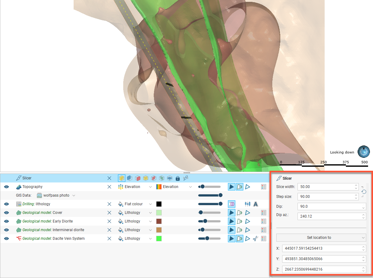
Slice the scene roughly where you want the drillhole to be drilled:
Adjust the slice orientation using the Dip and Dip az. controls in the slicer’s properties panel. You can also use the X, Y and Z fields to adjust the position:
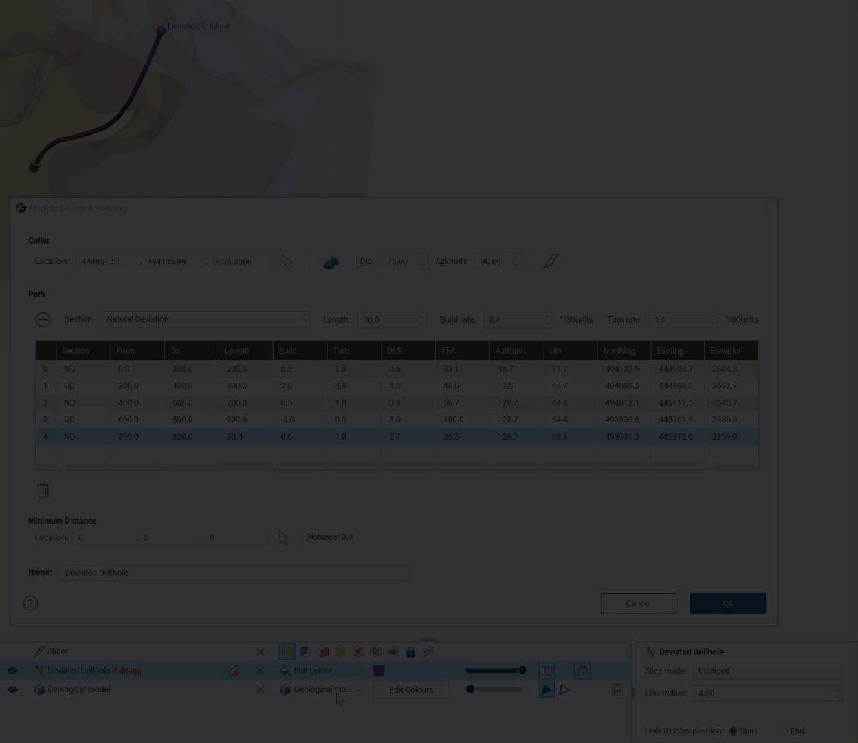
Right-click on the Planned Drillholes folder and select New Multiple Deviation Hole. The Multiple Deviation Planning window will open.
Changes you make in the Multiple Deviation Planning window are updated in the scene, so position the window in a way that allows you to see the scene. Note also that the drillhole has some special colouring options to indicate the Section type (natural or directed deviation) or the Dog Leg Severity.
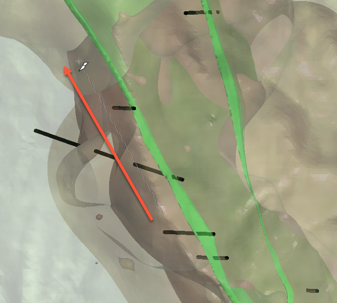
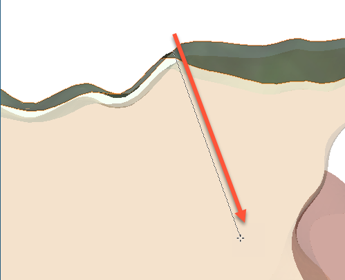
If an inclined start to the hole is required, you can draw the initial direction for the hole on the slicer. Click the Pick collar point button (![]() ) next to the Project to topography button (
) next to the Project to topography button (![]() ), then, on the slicer, click and drag from approximately where the collar should be located down on the initial drilling angle.
), then, on the slicer, click and drag from approximately where the collar should be located down on the initial drilling angle.
To rotate the scene so you can click on the slicer plane, press the L key to quickly orient the camera orthogonally towards the slicer.
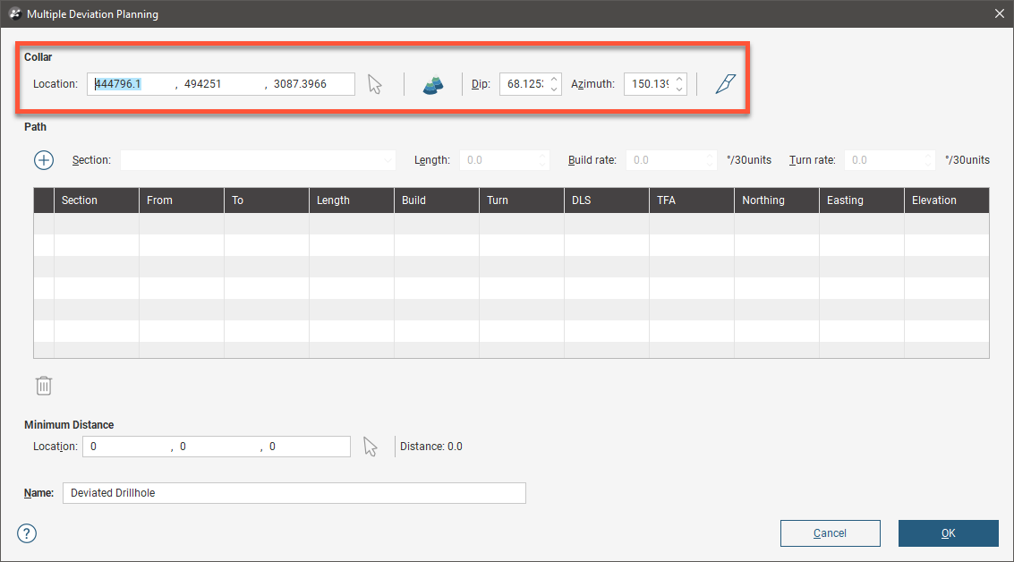
You will not see any object added to the scene yet, but the Collar location fields will have been updated. The Dip and Azimuth for the initial drilling direction can be adjusted.
Click the Project to topography button (![]() ) to shift the collar point to the ground surface. The Collar location fields will be updated.
) to shift the collar point to the ground surface. The Collar location fields will be updated.
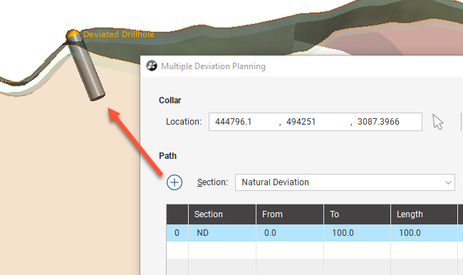
At this point, it can be helpful to add an initial section so there is an object in the scene to see. Click the Add a Section button (![]() ). The planned hole will appear in the scene on the slicer at the angle drawn earlier.
). The planned hole will appear in the scene on the slicer at the angle drawn earlier.
In the Multiple Deviation Planning window you can change the collar Location in the X, Y and Z coordinates and the orientation using the Dip and Azimuth fields. Clicking the Slice along button (![]() ) will then reorient the slicer using the collar location and Azimuth direction.
) will then reorient the slicer using the collar location and Azimuth direction.
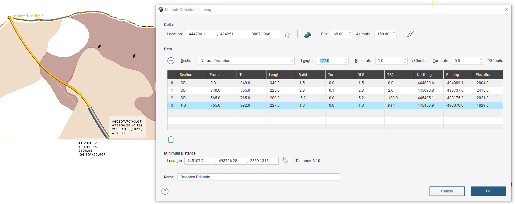
Adding Natural Deviation Sections
You may already have clicked the Add a Section button (![]() ) to get the initial drilling section to appear in the scene. If not, or if you are adding an additional section to the planned drillhole, click the Add a Section button (
) to get the initial drilling section to appear in the scene. If not, or if you are adding an additional section to the planned drillhole, click the Add a Section button (![]() ).
).
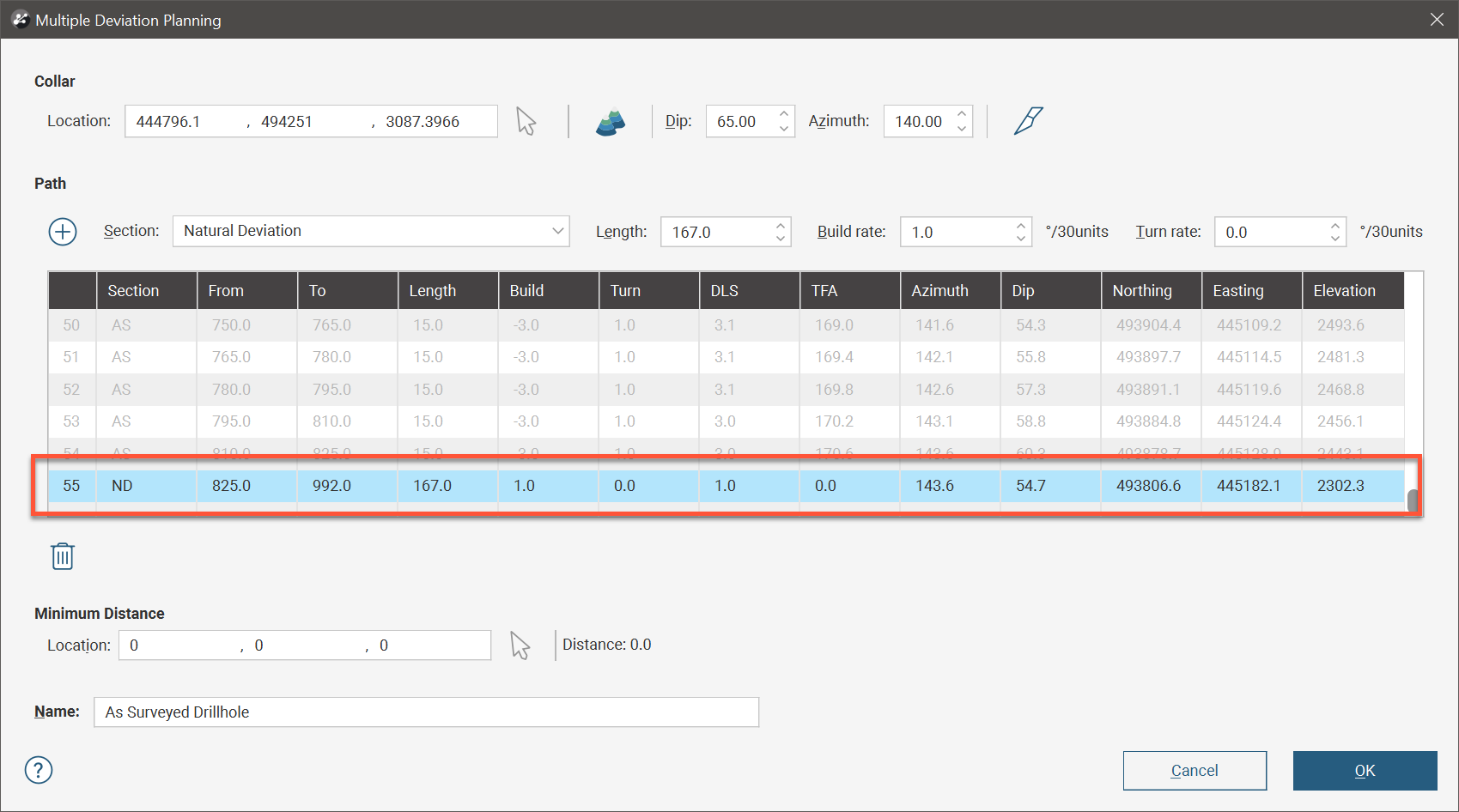
From the Section dropdown list, choose the Natural Deviation option, intended for modelling the expected behaviour of the drill in the rock. You can specify the expected Build rate and Turn rate based upon the rock type and orientation it will be drilling through.
Note that Build rate and Turn rate are described using ‘degrees per 30 units’. If you are using metric standards, this will be ‘degrees per 30 m’ and for those using imperial measures, ‘degrees per 30 ft’.
Having set the rate at which the hole will curve, you can adjust the section Length and observe the result on the planned deviated drillhole in the scene:

Adding Directed Deviation Sections
You may already have clicked the Add a Section button (![]() ) to get the initial drilling section to appear in the scene. If not, or if you are adding an additional section to the planned drillhole, click the Add a Section button (
) to get the initial drilling section to appear in the scene. If not, or if you are adding an additional section to the planned drillhole, click the Add a Section button (![]() ).
).
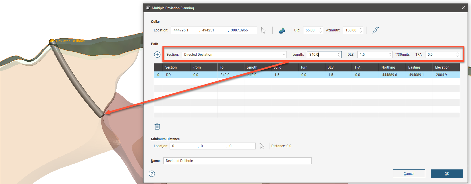
From the Section dropdown list, choose the Directed Deviation option, intended for planning a path for a steerable drilling system. You can specify the desired DLS (dogleg severity) and TFA (toolface angle) to direct the drill head.
Note that DLS is described using ‘degrees per 30 units’. If you are using metric standards, this will be ‘degrees per 30 m’ and for those using imperial measures, ‘degrees per 30 ft’.
TFA is set in degrees.
Having set the rate at which the hole will curve, you can adjust the section Length and observe the result on the planned deviated drillhole in the scene:
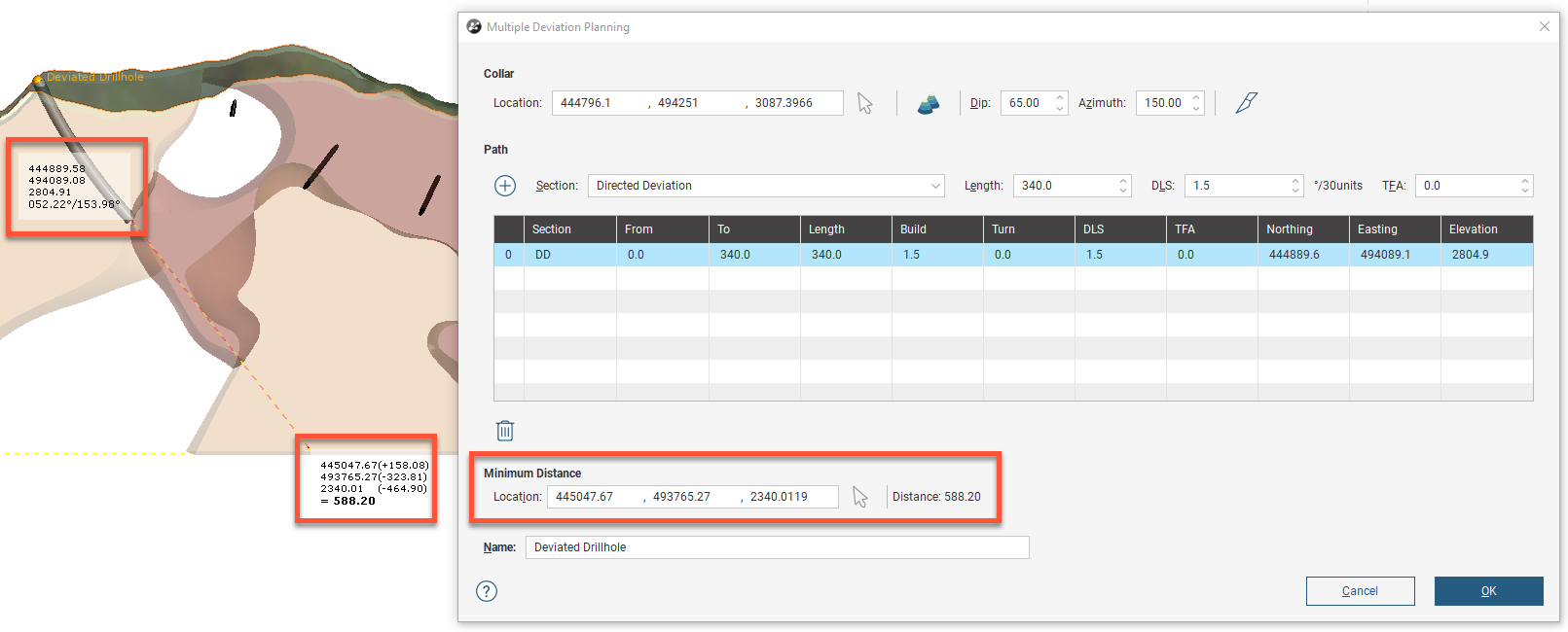
Show Distance, Azimuth and Dip to Target
In the Minimum Distance fields, you can set the location for a target you want planned multiple deviation hole to reach using X, Y and Z coordinates. Alternatively, you can click the Pick target button (![]() ) between the location fields and the Distance value, then click in the scene to set a target location. The Distance value will change to indicate the distance from the current end of the planned hole to the target.
) between the location fields and the Distance value, then click in the scene to set a target location. The Distance value will change to indicate the distance from the current end of the planned hole to the target.
To rotate the scene so you can click on the slicer plane, hit the L key to quickly orient the camera orthogonally towards the slicer.
In the scene, two sets of information are added, one at the end of the planned hole and the other at the target. At the end of the planned hole, the X, Y and Z coordinates of the end of the planned hole are identified, along with the azimuth and dip to the target. At the target, the X, Y and Z coordinates of the target are shown, along with the deltas on each axis from the end of the planned hole, and the straight line distance:
Adding Additional Deviation Sections
Click the Add a Section button (![]() ) to extend the planned drillhole with an additional section. It is possible to mix Directed Deviation and Natural Deviation sections.
) to extend the planned drillhole with an additional section. It is possible to mix Directed Deviation and Natural Deviation sections.
Viewing Drilling Prognoses
Evaluate any model in the project onto the planned multiple deviation drillhole by right-clicking on the multiple deviation hole in the project tree and selecting Evaluations. Move models to evaluate onto the planned hole by moving them from the Available list into the Selected list, then click OK.
Right-click on the multiple deviation hole in the project tree again and select Drilling Prognoses. A new dockable tab will open with the drilling prognoses table. Use the View prognoses for dropdown list to pick from the models evaluated onto the planned hole. Use the Merged Intervals option to combine the information from all evaluations.
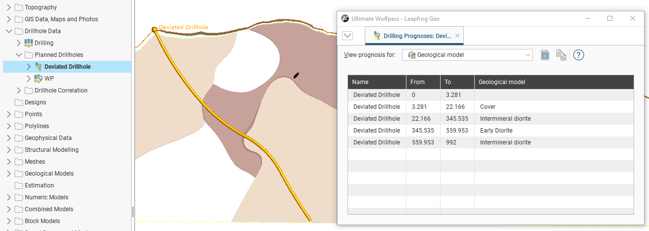
You can copy the information displayed to your computer’s clipboard by selecting rows, then clicking the Copy button (![]() ). You can select all the rows by clicking the Select All button (
). You can select all the rows by clicking the Select All button (![]() ).The information in the selected rows will be copied as tab delimited text, which can be copied into a spreadsheet application such as Excel.
).The information in the selected rows will be copied as tab delimited text, which can be copied into a spreadsheet application such as Excel.
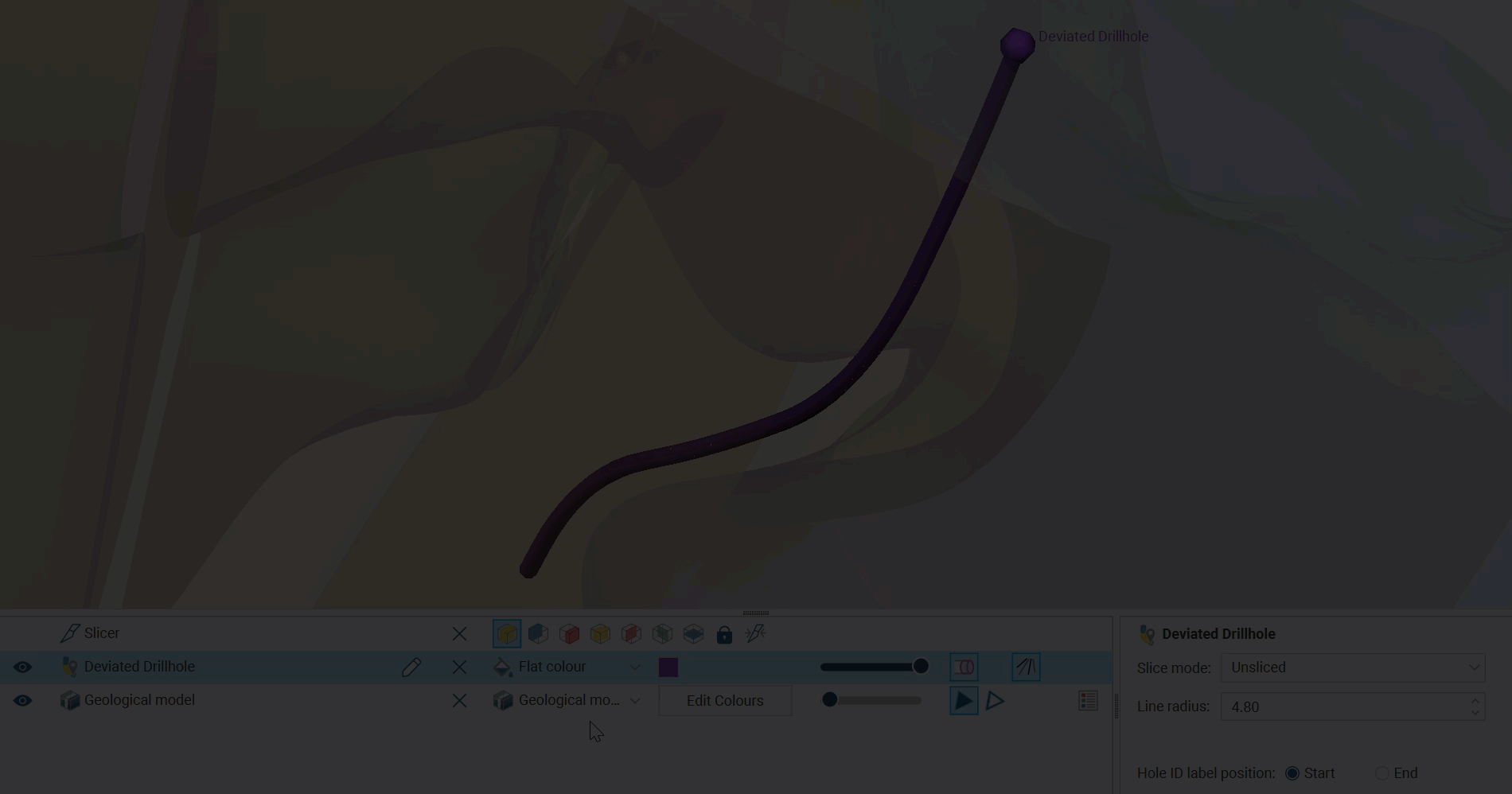
Viewing Dog Leg Severity
When a multiple deviation planned drillhole is viewed in the scene, you can visualise the Dog leg severity or the Section type for each interval. From the shape list, set the colouration to Dog leg severity or Section type.
Exporting Planned Deviated Drillholes
There are four ways to export information from planned multiple deviation drillholes:
Exporting as Interval Tables
A planned multiple deviation drillhole can be exported as interval tables in *.csv format. To do this, right-click on the drillhole and select Export as Interval Tables. In the Export Directional Drillhole Tables window, the files that will be created are listed, one each for the collar and survey table and one for the evaluations:
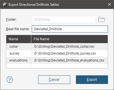
Change the Base file name, if required, choose a folder in which to save the files, then click Export to save the files.
Exporting as Points
A planned multiple deviation drillhole can be exported as a points table in *.csv format. The file will contain X, Y and Z values, along with measured depth (MD) and true vertical depth (TVD) columns. Any evaluations on the drillhole can also be included.
To export a planned drillhole as points, right-click on the drillhole and select Export as Points. In the window that appears, select where you wish to save the file, enter a file name and then click Save. Next you will be prompted to select which evaluations to include:
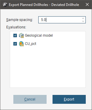
Set the Sample spacing and the evaluations you require, then click Export.
Exporting as a Polyline
A planned drillhole can be exported as a polyline the following formats:
- Leapfrog Polylines (*.lfpl)
- Leapfrog Mining Polylines (*.csv)
- Drawing Interchange Polylines Files (*.dxf)
- Surpac String Polyline Files (*.str)
- Gocad Polylines Files (*.pl *.ts)
- MineSight Polylines Files (*.srg)
- Datamine Polylines Files (*.asc)
- Micromine Polylines Files (*.str *.asc)
- AutoCAD Drawing Files (2013/LT2013) (*.dwg)
- Bentley Drawing Files (v8) (*.dgn)
To export a planned drillhole as a polyline, right-click on the drillhole and select Export as Polyline. In the window that appears, select where you wish to save the file, enter a file name, select the file type from the Save as type options, and then click Save.
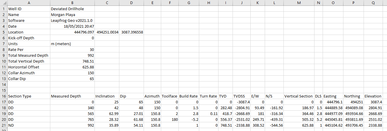
Exporting a Drilling Plan
A drilling plan can be exported for a planned multiple deviation drillhole. To do this, right-click on the drillhole and select Export Drilling Plan. In the window that appears, select where you wish to save the file, enter a file name and then click Save. The file will then be saved as a CSV file.
Importing a Drilling Plan
Leapfrog Geo imports planned multiple deviation drillholes from files in *.csv format.
To import a drilling plan, right-click on the Planned Drillholes folder and select Import Multiple Deviation Drilling Plan. Select the file and click Open. If there are no conflicts, the planned drillhole will be added to the Planned Drillholes folder and will be opened in the Multiple Deviation Drillhole Planning window.
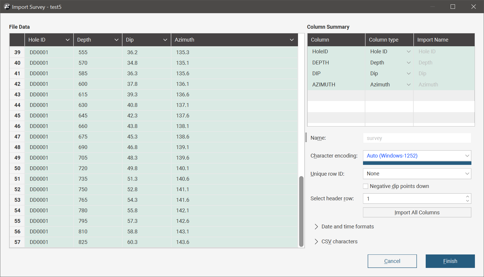
Importing an As-Drilled Drillhole Survey
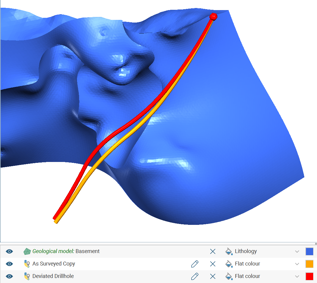
Once a planned drillhole is drilled, survey data can be entered in to monitor progress, as the surveyed drillhole data may not correspond exactly to the plan. By importing the surveyed drillhole data into a planned drillhole, the forward trajectory of the drilling can be redesigned for the remainder of the drilling to make corrections and work toward the target, as necessary. To add the survey data, right-click a planned drillhole in the project tree and select Import Survey from the pop-up menu, then select the file containing the survey data.
Once you click Finish the Multiple Deviation Planning window will be opened so the remainder of the drillhole can be planned. If the as-surveyed drillhole is shallower than the originally planned drillhole, an additional planned interval extending past the last interval out to the originally planned depth will have been added to the path table. This interval can be deleted or modified as necessary.
To get a side-by-side comparison between the originally planned hole and the as-drilled hole, take a copy of the planned drillhole and import the survey file into the copy of the planned drillhole. Add both to the scene to view side-by-side for comparative purposes. If the originally planned drillhole is no longer required, it may be deleted.