
Polylines
Leapfrog Geo imports many common polyline formats and also has tools for drawing and exporting polylines. This topic describes:
- Creating Polylines
- Displaying Polylines
- Sharing and Unsharing Polylines
- Importing Polylines
- Reloading Polylines
- Adding Attributes to Polylines
- Viewing the Polyline Attributes Table
- Exporting Polylines
See Drawing in the Scene for information on drawing and editing polylines.
Creating Polylines
There are four ways to create polylines in Leapfrog Geo:
- Create a new polyline using the Polylines folder. These polylines are stored in the Polylines folder.
- Create a new polyline as part of working with another tool. For example, a polyline can be drawn to create a lateral extent in a geological model. These polylines are stored in the tool used to create them and cannot be used elsewhere in the project unless they have been shared. To share a polyline, right-click on it and select Share. The polyline will be moved to the Polylines folder and can be used elsewhere in the project.
- Create a new polyline from a GIS line. To do this, right-click on the GIS lines object (
 or
or  ) in the GIS Data, Maps and Photos folder and select Extract Polyline. The new polyline object will appear in the Polylines folder. It is not linked to the original GIS lines object.
 - Extract lines from a design or alignment in the Designs folder. To do this, right-click on a lines object (
 ,
,  ,
,  or
or  ) in a design and select Extract Polyline. The new polyline object will appear in the Polylines folder. It is not linked to the original design.
See Drawing in the Scene for information on drawing and editing polylines.
Displaying Polylines
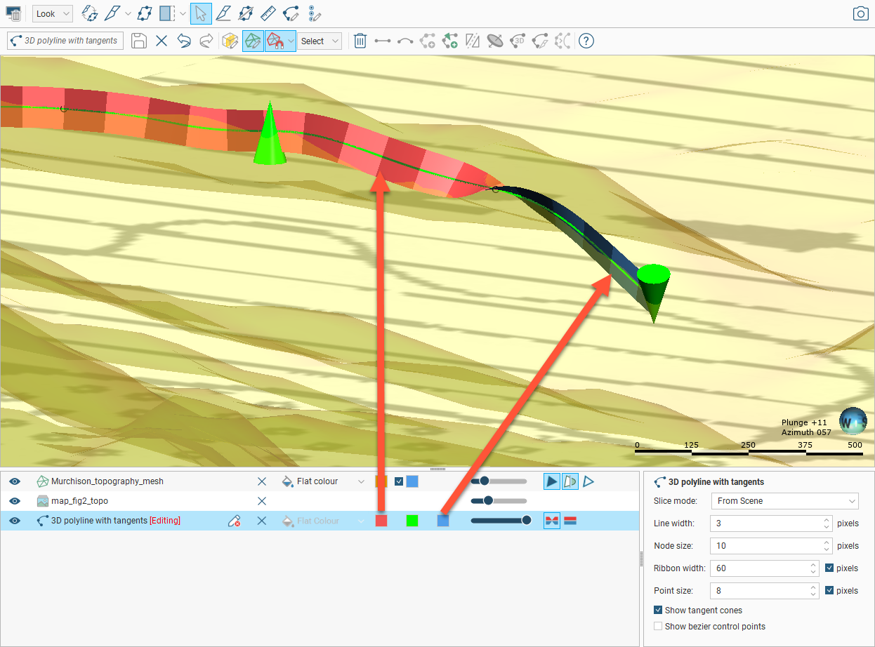
When polylines are displayed in the scene, you can control the colour of the positive and negative surfaces of the line and of the line itself. In this example, the positive side of the polyline is red, the negative side is blue and the polyline itself is green:
For contact surfaces, the colour of the positive and negative sides of a ribbon will be determined by the lithologies or categories assigned to either side of the surface.
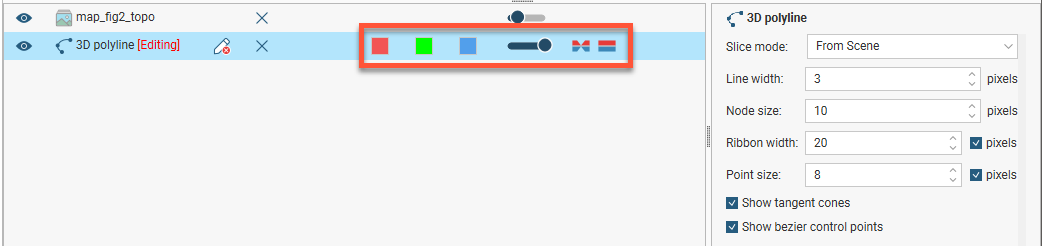
With the Node size and Point size controls in the properties panel, you can change the size of nodes and points in the scene to make working with the polyline easier.
Polylines have a Surface ribbon(![]() ) and Normal ribbon(
) and Normal ribbon(![]() ) to help you to determine the orientation of the polyline in the scene. The surface ribbon reflects the orientation of the polyline and the normal ribbon is perpendicular to the surface ribbon. For example, click on the Surface ribbon button (
) to help you to determine the orientation of the polyline in the scene. The surface ribbon reflects the orientation of the polyline and the normal ribbon is perpendicular to the surface ribbon. For example, click on the Surface ribbon button (![]() ) to determine which side of the polyline is positive (red) and which side is negative (blue):
) to determine which side of the polyline is positive (red) and which side is negative (blue):
If you are having trouble seeing the ribbons, you can change their size using the Ribbon width control in the properties panel.
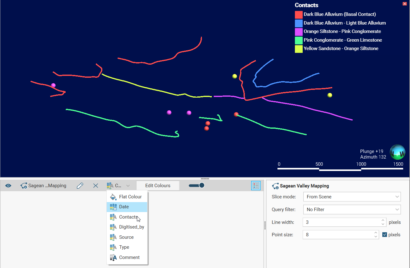
By default, polylines are displayed using the Flat Colour option. The view list will also include attributes, if the polyline has any. To view a polyline by an attribute, choose that attribute from the view list. Here a polyline is displaying using a category attribute called Contacts:
Other aspects of polyline display are useful when creating and editing polylines. See Drawing in the Scene.
Sharing and Unsharing Polylines
Some polylines are created as part of working with other objects and are not available elsewhere in the project. An example of this is a polyline drawn as part of creating a model boundary. To share the polyline, right-click on the object in the project tree and click Share. The shared polyline will be copied to the relevant location in the project tree and a hyperlink added to the object it was shared from.
Polylines that have been shared can be unshared by making a local copy of the polyline. To do this, right-click on the shared polyline and select Create Local Copy:
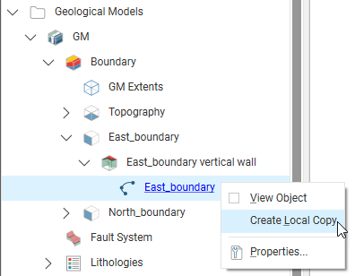
The polyline in the Polylines folder remains, but a local copy of it is made and the hyperlink to the Polylines folder copy is deleted. This means you can now work on, for example, the Polylines folder copy without changes to it affecting the geological model’s copy.
Importing Polylines
Polyline formats Leapfrog Geo supports include:
- AutoCAD Drawing Files (2013/LT2013) (*.dwg)
- Bentley Drawing Files (v8) (*.dgn)
- Datamine Polyline Files (*.asc)
- Drawing Interchange Polylines Files (*.dxf)
- Gemcom Polylines (*.asc)
- Leapfrog Polylines (*.lfpl)
- Leapfrog Straight Polylines (*.csv)
- Micromine Polylines (*.str, *.asc)
- MineSight Polylines (*.srg)
- Old Leapfrog Polylines (*.csv, *.txt)
- Surpac String Polylines (*.str)
There are two ways to import a polyline:
- Right-click on the Polylines folder and select Import Polyline. In the Import Polyline window, navigate to the location where the polyline file is saved and select it. Click Open.
- Drag and drop polyline files directly into Leapfrog Geo.
If the polyline file is in Leapfrog Polyline *.lfpl format or one of the computer-aided design formats, the importing will start immediately.
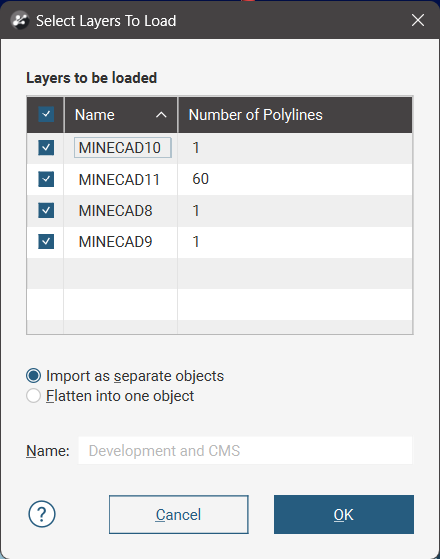
When importing a file that has multiple features, you will be prompted to select which ones to import. You can also choose to:
- Import the features as separate objects. Each feature will appear in the project tree as a separate object.
- Flatten all features into one object. Leapfrog Geo will treat all features as a single object.
For all the delimited character formats, the Import Polyline window will appear showing the data in the file.
See the Working With Data Tables topic for information on mapping the data in the file to the format Leapfrog Geo expects for polylines.
Each polyline consists of a series of vertices, with each row representing a vertex location. Line segments that make up the polyline are drawn between the listed vertices. Vertices that make up each polyline are grouped, with the start of a polyline sequence being coloured red in the Import Polyline window. Subsequent vertices that make up the polyline are coloured green. If there are no green subsequent rows shown in the Import Polyline window, these are points that are treated as polylines, but will appear as points in the scene.
If the format of the data file being imported uses separator rows to group the vertices that make up a polyline, make sure that the Row option is selected under Separate polylines by. Then use Row starts with to specify the character that marks a row as a polyline separator:
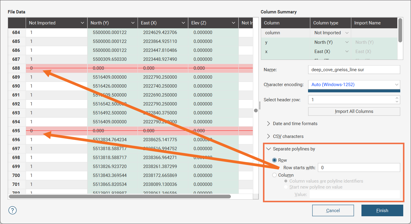
The red highlighted row with the red strike-through line marks the separator recognised by the initial character in the row. The rows between mark the vertices for the line segments of the polyline.
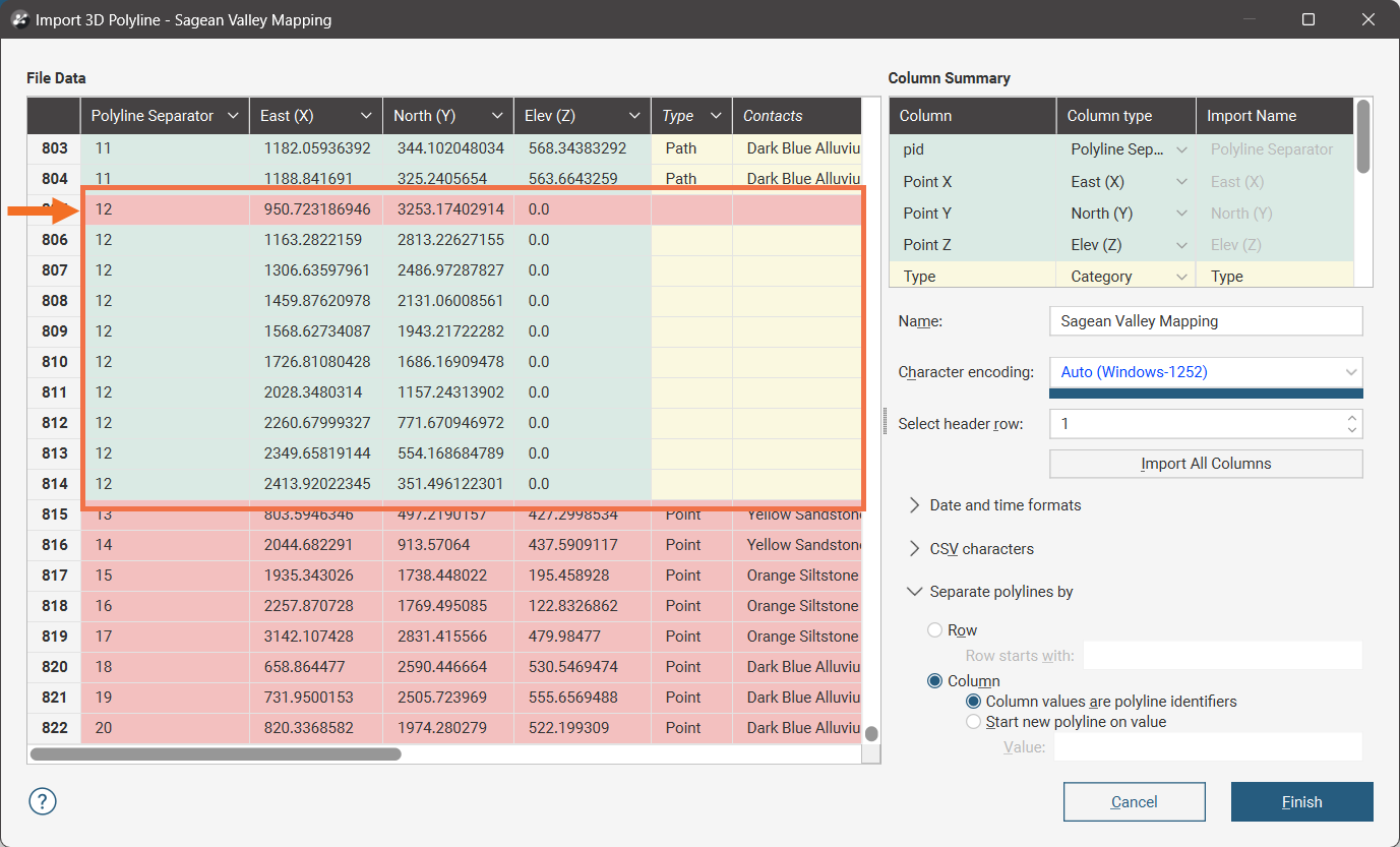
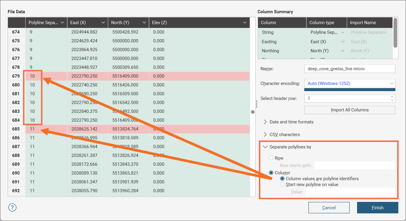
If the format of the data file being imported uses a 'string ID' as a polyline identifier number that each vertex in the polyline shares, make sure that the Column option is selected under Separate polylines by. Then select the Column values are polyline identifiers option to indicate that a data column will store the polyline identifier. If the identifier code for the polylines is not automatically recognised, select Polyline Separator from the dropdown list in the header for the appropriate column. For example, here the red highlighted row marks the starting vertex of the polyline with the string ID 10:
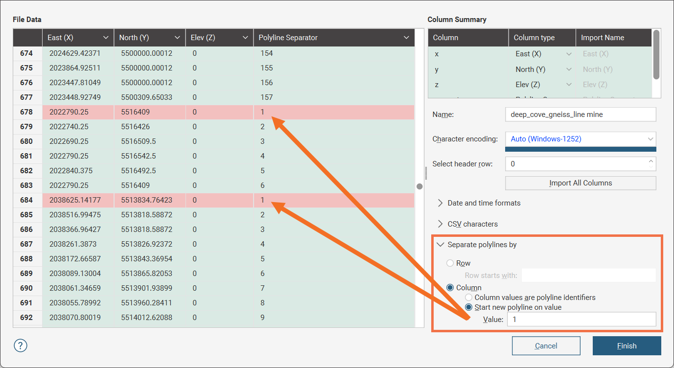
If the format of the data file being imported uses a 'point ID' that marks each vertex in a polyline with a number in sequence, make sure that the Column option is selected under Separate polylines by. Then select the Start new polyline on value option to indicate that a data column will store the point IDs, and specify the value that marks the start of a new polyline, usually 0 or 1. If it is not automatically recognised, select Polyline Separator from the dropdown list in the header for the appropriate column. For example, here the red highlighted row marks the starting vertex of the polyline:
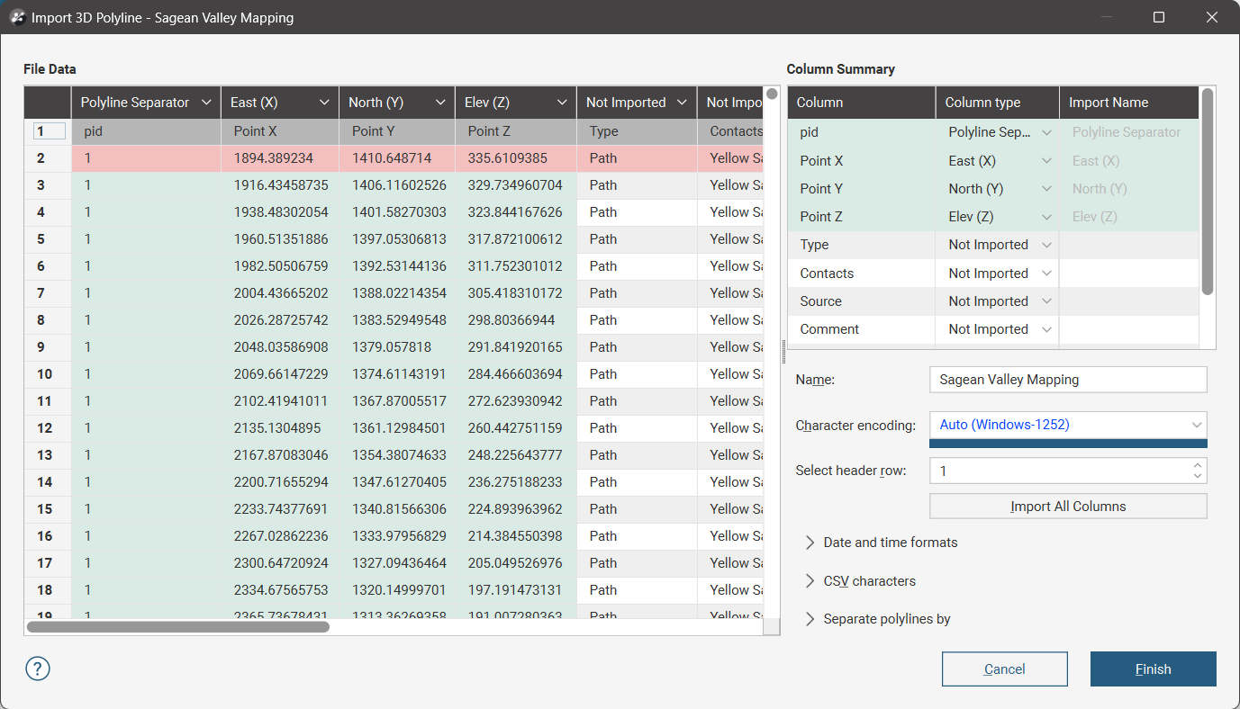
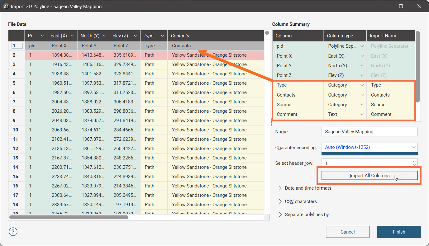
Besides the locations for vertices that make up a polyline, a polyline file can also contain attributes pertaining to the polylines. If these attributes are present as additional columns, each can be added by selecting the appropriate Column type in the Column Summary table. Click the Import All Columns button to automatically add all the additional columns and auto-select column types, overriding the automatic selections if necessary.
The polyline will be imported and added to the project tree under the Polylines folder.
See Drawing in the Scene for information on drawing and editing polylines.
Reloading Polylines
Reloading data is necessary when the imported data is modified externally. To reload a polyline, right-click on it in the project tree and select Reload Data.
Reloading a polyline discards any changes you have made to the polyline, including any attributes you have added. Any dependent objects will be updated, which can take some time.
Select the file to be reloaded and click Open. The polyline will be updated, as will any dependent objects.
Adding Attributes to Polylines
It is possible to add attributes to polylines; this adds a new column to the polylines object.
Only category attributes can be added to polylines.
To start adding category attributes to polylines, right-click on the polylines object in the project tree and select New Category Selection. The New Category Selection window will appear:
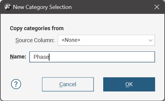
- If you select <None> for the Source Column, a new Name column with no category assignments will be added to the polyline. You can then select polylines and assign them to categories.
- If you select an existing column as the Source Column, the existing column will be linked to the new Name column using the existing data category assignments. You can then select polylines and assign them to existing categories or new categories.
You can change the categories assigned to polylines in the new column, but categories inherited from the Source Column cannot be renamed.
When you click OK, the polylines object will be added to the scene, along with a set of tools for selecting polylines.
The first four tools in the category selection toolbar are the primary tools for selecting polylines in the scene:
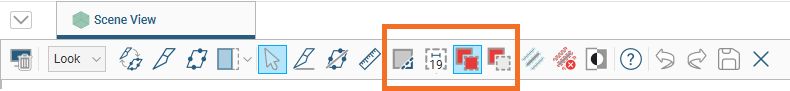
The Select Polylines tool (![]() ) is for drawing across polylines in the scene. This tool adds polylines to or removes them from the current selection, depending on which of the Add Polylines(
) is for drawing across polylines in the scene. This tool adds polylines to or removes them from the current selection, depending on which of the Add Polylines(![]() ) or Remove Polylines(
) or Remove Polylines(![]() ) tools is also enabled:
) tools is also enabled:
- If Add Polylines(
 ) is enabled, drawing across polylines adds them to the current selection.
 - If Remove Polylines(
 ) is enabled, drawing across polylines removes them from the current selection. Drawing across unselected polylines will have no effect.
Selected polylines are highlighted in the scene.
You can change the width of the line used by the Select Polylines tool by clicking on the second button in the toolbar:
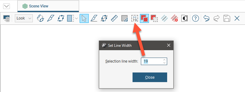
The number shown as part of the Change line width button is the currently set line width.
You can keep this window open while selecting polylines so you can increase the line width to choose more polylines or reduce the line width to select fewer polylines.
You can also:
- Select all visible polylines by clicking on the Select all button (
 ) or by pressing Ctrl+A.
 - Clear all selected polylines by clicking on the Clear selection button (
 ) or by pressing Ctrl+Shift+A.
 - Swap the selected polylines for the unselected points by clicking on the Invert selection button (
 ) or by pressing Ctrl+I.
Click the Assign to button. If there are existing category types, these will appear at the bottom of the list for selection.
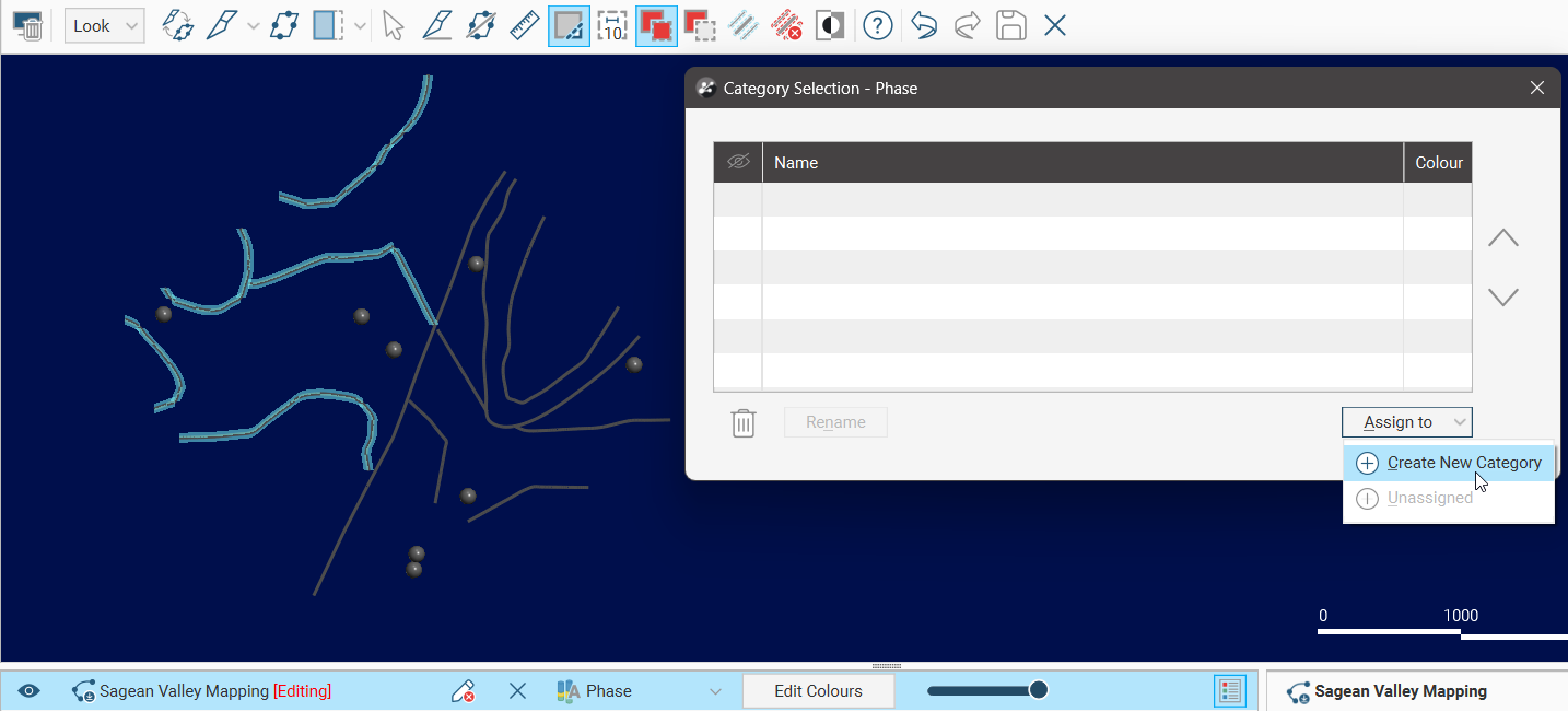
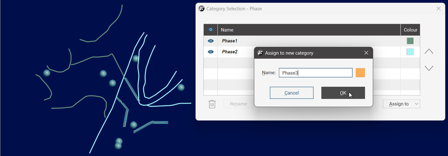
You can also select Create New Category from the options. In the Assign to a new category window, supply a Name for the new category.
When you are finished, click the Save button (![]() ).
).
The new category column will appear in the project tree as an additional column on the polyline table. Select the new column from the shape list to display it.
Viewing the Polyline Attributes Table
To view the polyline attributes, right-click on the polylines object in the project tree and select Attribute Table. This displays a read-only view of the polyline object table.
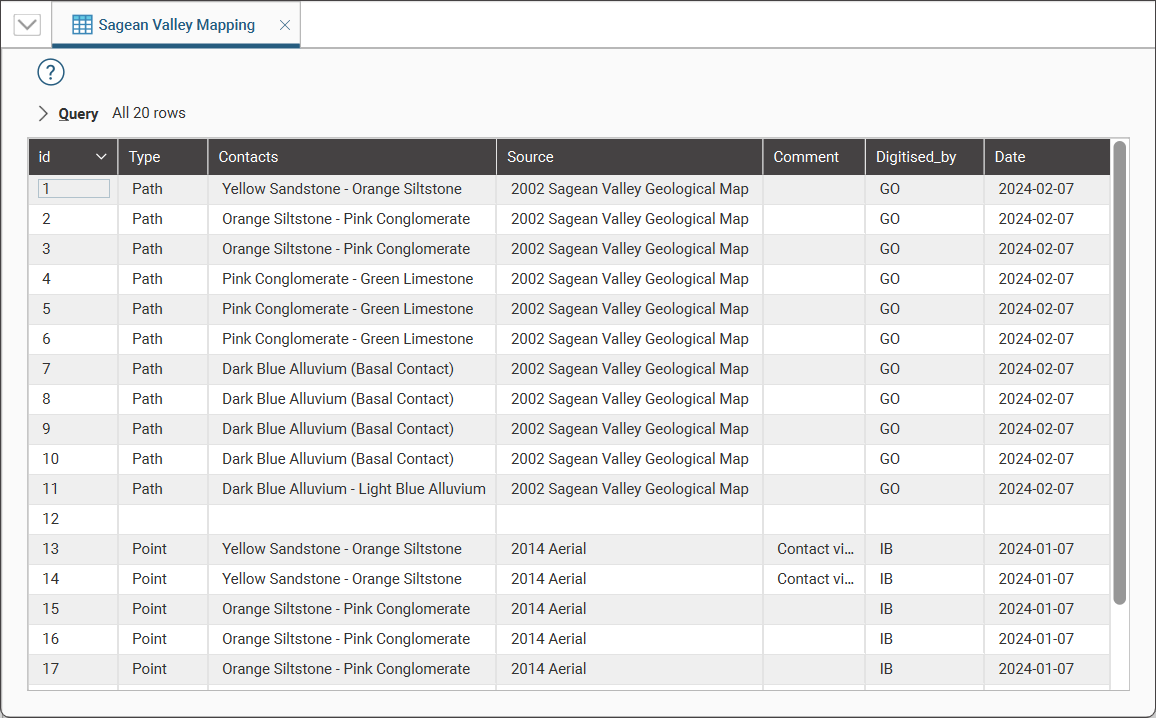
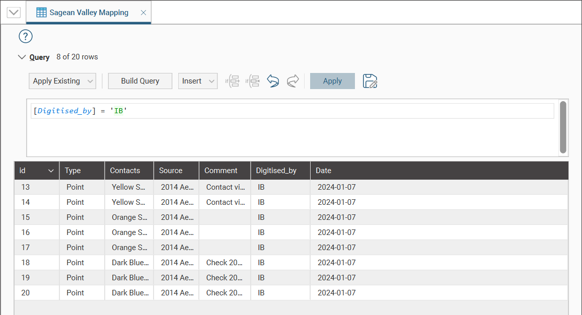
Use the Query tool to filter the table to find objects of particular interest.
Exporting Polylines
Export a polyline by right-clicking on it and selecting Export. Leapfrog Geo exports polylines in the following formats:
- Leapfrog Polylines (*.lfpl)
- Leapfrog Straight Polylines (*.csv)
- Leapfrog Mining Polylines (*.csv)
- Drawing Interchange Polyline Files (*.dxf)
- Surpac String Polylines Files (*.str)
- Gocad Polylines Files (*.pl, *.ts)
- MineSight Polylines Files (*.srg)
- Datamine Polylines Files (*.asc)
- Micromine Polylines Files (*.str, *.asc)
- AutoCAD Drawing Files (2013/LT2013) (*.dwg)
- Bentley Drawing Files (v8) (*.dgn)
Only the Leapfrog Straight Polylines (*.csv) file format supports the exporting of a polyline with attributes. As the name suggests, this format does not preserve bezier curves, but these are re-modelled using small straight line segments.