
Drillhole Groups
With the drillhole planner, planned drillholes are created within a drillhole group. The advantage of planning drillholes in this way is that all planned drillholes can share a naming convention and default path values. Models can be evaluated onto the group as a whole in order to view drilling prognoses, and some or all drillholes in a drillhole group can be exported at once.
Within a planned drillhole group, there are two methods for defining the drillholes in the group:
- The single hole method. Planned drillholes are defined one by one, with the collar and/or target specified and the path adjusted before moving on to the next hole. With this method, it is possible to define a series of drillholes using the same path at regular offsets.
- The grid method. A grid of drillholes is created using common extents and uniform spacing and path values. Once the grid is created, each drillhole in the group can be adjusted on an individual basis. This method is a shortcut for defining a large quantity of drillholes in a specific area before making any required drillhole-by-drillhole adjustments; once the grid is created, you cannot edit it. However, you can create subsequent grids if, say, you are defining a group of planned drillholes for a nearby area.
You are not limited to using only one method for a given planned drillhole group.
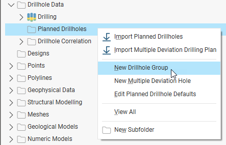
Whichever method you plan to use, start by right-clicking on the Planned Drillholes folder and selecting New Drillhole Group:
This topic describes how to define planned drillholes within a drillhole group, view drilling prognoses and export planned drillholes in different formats. It also describes how to import planned drillholes into an existing drillhole group or into a new group.
The rest of this topic is divided into:
- Working With Drillhole Groups
- Setting Drillhole Planning Defaults
- Using the Single Hole Method
- Using the Grid Method
- Viewing Drilling Prognoses
- Exporting Planned Drillholes
- Importing Planned Drillholes
Working With Drillhole Groups
A drillhole group acts as a container for the drillholes in a drilling campaign.
Creating a Drillhole Group
To create a drillhole group, right-click on the Planned Drillholes folder and select New Drillhole Group. In the Drillhole Group window, you can change the Prefix that will be used in naming each drillhole that will be added to the group.
Displaying Planned Drillholes
Once there are planned drillholes in the group, you can display the group in the scene. Do this by dragging the group from the project tree into the scene. To control what drillholes are displayed in the scene, open the group and use the show/hide buttons (A):
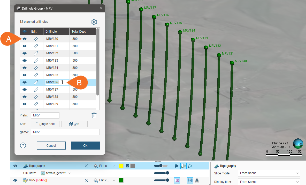
You can edit a drillhole‘s name in this window by double-clicking on it (B).
Search for planned drillholes in the list by pressing Ctrl-F. A Find window will appear that you can use to search the list.
To update a drillhole, click its Edit button.
Deleting Planned Drillholes
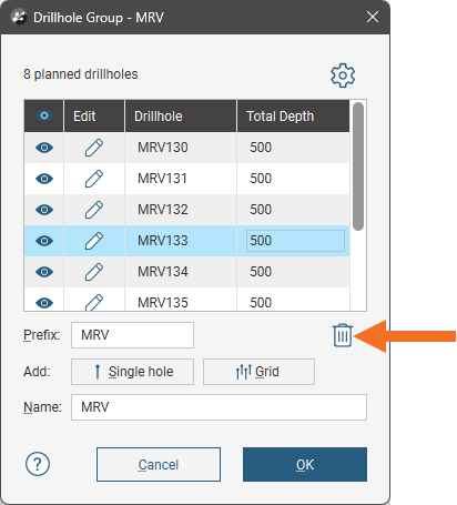
To delete a planned drillhole, click on it in the list, then click the Delete button:
Moving Planned Drillholes to Another Group
You can move planned drillholes to a different group by opening both groups, then dragging drillholes between the groups.
For example, here the drillholes selected in the first group are being copied into the second group:
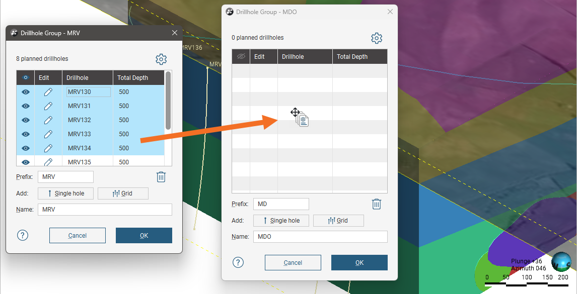
This makes copies of the selected drillholes in the other group without removing them from the original group. You will need to delete the planned drillholes from the group you copied them from.
Evaluating Models on Planned Drillholes
Any model in the project can be evaluated on a drillhole group, and evaluations can be exported when the group is exported as interval tables. See Exporting Planned Drillholes. Right-click on the group in the project tree and select Evaluations. The Sample Distance setting applies to numeric evaluations and determines the spacing between downhole evaluation points.
Defining Filters for Planned Drillholes
You can also define filters for a drillhole group. A filter makes it easier to select a subset of the drillholes when the group is displayed in the scene. To define a filter, right-click on the group and select New Filter. Select which drillholes to include in the filter and enter a name for it. The filter will be saved in the project tree as part of the group.
Setting Drillhole Planning Defaults
Drillhole planning defaults are set on a per-project basis, and when you are starting to plan a new drilling campaign, it is a good idea to update the default drilling values before you start adding drillholes to a group. You can do this from the Drillhole Group window by clicking the settings button (![]() ):
):
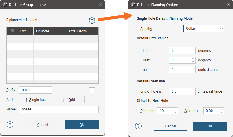
There are three planning modes available:
- Collar. The collar serves as the starting point in defining the drillhole. This mode suits scenarios where the drilling site is the primary constraint. Specify the collar’s location, dip and azimuth, along with the path. The target’s parameters will be calculated using the collar and path parameters. You can define the collar’s location by clicking in the scene or by entering the coordinates in the Drillhole Planning window.
- Target. The target serves as the starting point in defining the drillhole. This mode suits scenarios where drilling to a particular contact, zone or depth is the primary consideration and the collar location is not the primary constraint. Specify the target and its path; the drillhole‘s collars parameters will be calculated from the target and path. You can define the target’s location by clicking in the scene or by entering the coordinates in the Drillhole Planning window.
- Collar & Target. In this mode, both the collar and target locations are constrained and flexibility is achieved by varying the dip and azimuth for both. Specify the location of both the collar and target, along with the lift, drift and end of hole distance for the path. The dip and azimuth for both the collar and the target will be adjusted to ensure the specified locations of the collar and target. You can define both the collar and target locations by clicking in the scene or by entering the coordinates in the Drillhole Planning window.
Choose which mode you will be using for the drillhole group.
Next, set the Default Path Values:
- Lift is how much the drillhole deviates upward.
- Drift is how much the drillhole deviates laterally.
The Default Extension is the length by which the drillhole extends past the Target location.
The Offset To Next Hole values apply when defining multiple drillholes in the Drillhole Planning window.
Enter the information required and click OK. The new settings will be applied to the next new planned drillhole added to a drillhole group.
Using the Single Hole Method
To plan a drillhole in a drillhole group using the single hole method, add the data objects to the scene that you will use in defining the planned drillholes, such as any existing drillholes and surfaces that represent the collar and target locations. Open the drillhole group or create a new one by right-clicking on the Planned Drillholes folder and selecting New Drillhole Group.
Set the Prefix to be used for each drillhole that will be added to the group, and update the drilling defaults, if necessary.
To add the first drillhole, click the Single hole button (A). This opens the Drillhole Planning window (B), with an initial drillhole displayed in the scene (C).
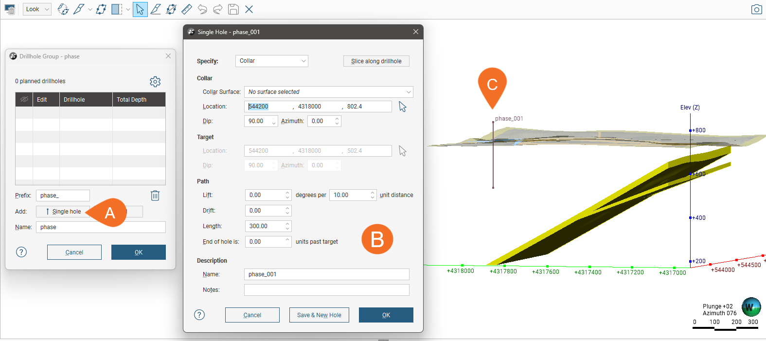
The new drillhole has a Name that uses the Prefix set in the Drillhole Group window. You can add a Note about this drillhole that will be visible in the scene details panel when the drillhole is clicked on in the scene.
This initial drillhole uses the default planning mode and the parameters set for the project in the Drillhole Planning Options window.
As you work in this window, note that the changes you make to:
- The planning mode
- The Collar Surface
- The Path settings
will be retained when you click Save & New Hole in order to create another drillhole. This makes it easy to set up a series of planned drillholes. You can change the default values used for the first drillhole in the Drillhole Planning Options window.
There are three planning modes you can use in this window, specifying the Collar, specifying the Target or specifying both Collar & Target.
The planning mode determines which parameters you can change in this window:
- For Collar mode, you cannot edit the target’s settings, which are calculated from the collar and path settings.
- For Target mode, you cannot edit the collar’s parameters, although you can choose a Collar Surface that will be used in setting the collar elevation.
- For Collar & Target, you cannot edit the dip and azimuth values for the collar and target. As with Target mode, you can choose a Collar Surface.
To specify the collar and/or target location you can:
- Enter coordinates in the Drillhole Planning window.
- Click on the button for the collar/target and then click in the scene where you wish to add the collar/target.
Entering coordinates and clicking in the scene both set the collar or target location in the scene and display a path calculated using the parameters in the Drillhole Planning window. In both cases, drawing a slice in the scene can help in adjusting the drillhole and in defining subsequent drillholes. To do this, click the Slice along drillhole button
You can also use the collar/target button to ‘draw’ the path of the drillhole in the scene. To do this, click the button for the collar/target, then click in the scene without releasing the mouse button. Drag to define the Path and release the mouse button when you have reached the target.
Once you have finished defining the drillhole, you can save the drillhole and close the planning window or keep the planning window open and create a new drillhole.
- To keep adding drillholes to the drillhole group, click Save & New Hole. The current drillhole will be saved and the Single Hole window will open for a new drillhole created at the Offset To Next Hole distance specified in the Drillhole Planning Options window. The planning mode, Collar Surface and Path settings used will be those used for the previous hole.
- To close the current drillhole, click OK. The drillhole will be saved to the group and its window closed, returning you to the Drillhole Group window.
Here the planning mode (D) is Collar and the initial Location values (E) create a drillhole in the scene (F):
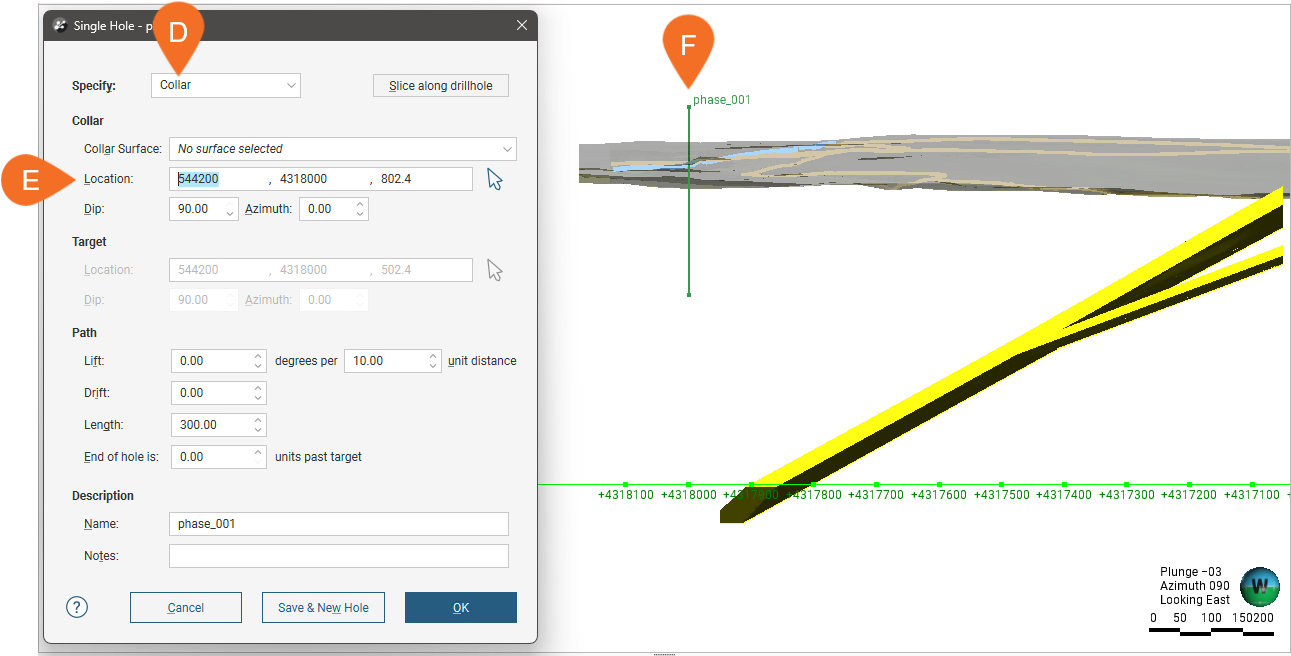
Note that the collar location is above the topography surface displayed in the scene. To make sure the location lies on the topography, select a surface from the Collar Surface list (G):
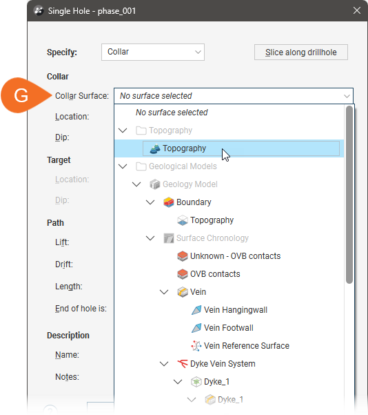
This moves the collar onto the selected surface.
Using the Grid Method
With the grid planning method, a grid of drillholes is created using common extents and uniform spacing and path values. Once the grid is created, each drillhole in the group can be adjusted on an individual basis. This method is a shortcut for defining a large quantity of drillholes in a specific area before making any required drillhole-by-drillhole adjustments; once the grid is created, you cannot edit it. However, you can create subsequent grids if, say, you are defining planned drillholes for a nearby area and wish to keep them in one drillhole planning group.
To plan a grid of drillholes, create a new planned drillhole group or open an existing one. Add the data objects to the scene that you will use in defining the planned drillholes, then click the Grid button (A). This opens the Drillhole Group Grid window (B), with a grid and controls displayed in the scene (C). The number of drillholes that will be created within the grid’s extents is determined by the Spacing values, with the total number of holes indicated (D).
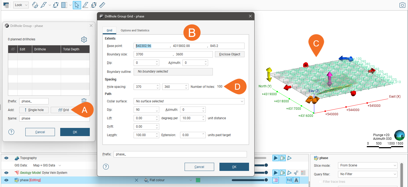
The grid created in this window is not saved in the project tree and so cannot be edited. Clicking OK closes this window and creates the drillholes specified by the grid, adding them to the drillhole group. Although you cannot edit this grid once it has been closed, you can create another grid to add more drillholes to the drillhole group.
In the scene, each drillhole that will result from creating the grid is displayed. Changes you make in the Drillhole Group Grid will be reflected in the scene.
Use the controls in the scene to set the extents of the grid:
- The orange and pink handles set the Base point values.
- The red handles adjust the Boundary size.
- The yellow handle adjusts the Dip.
- The blue handle adjusts the Azimuth.
The grid extents are intended to include complete blocks defined by the Hole spacing values, and so when changes are made to the grid size in the scene, the grid will ‘snap’ so that complete blocks are maintained.
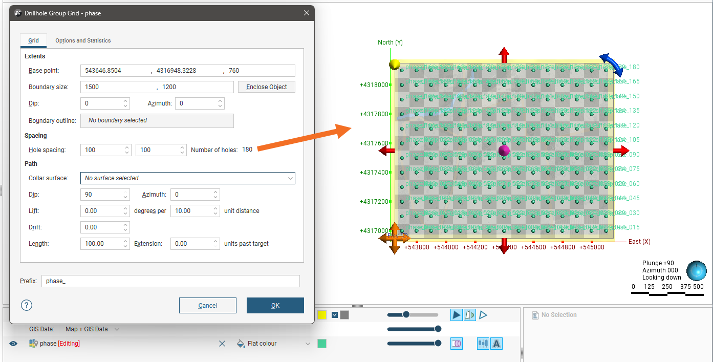
Here the extents have been adjusted to be slightly larger than the topography (in yellow) and the Hole spacing has been adjusted to create more drillholes:
Projecting Collars Onto a Surface
To make sure all collars in the grid lie on, for example, the topography, you can choose a Collar surface from those available in the project.
Using a Target Surface
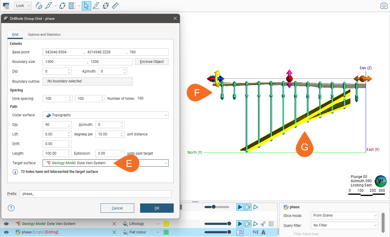
You can choose a surface or volume in the project to use to determine the target for each planned drillhole in the grid. If you use a volume as the Target surface, the last point at which each drillhole intercepts the surface will be used as the target point.
Here, we have used a vein system volume as the Target surface (E). Where the drillholes in the grid do not intercept the surface (F), the drillhole length is determined by the Length value set. Where the drillholes do intercept the surface (G), the target is the last intercept point.
Using a Boundary Outline
You can use any polyline or GIS line in the project to define the area in which drillholes will be created.
Here a polyline is used to define two areas in which drillholes will be created:
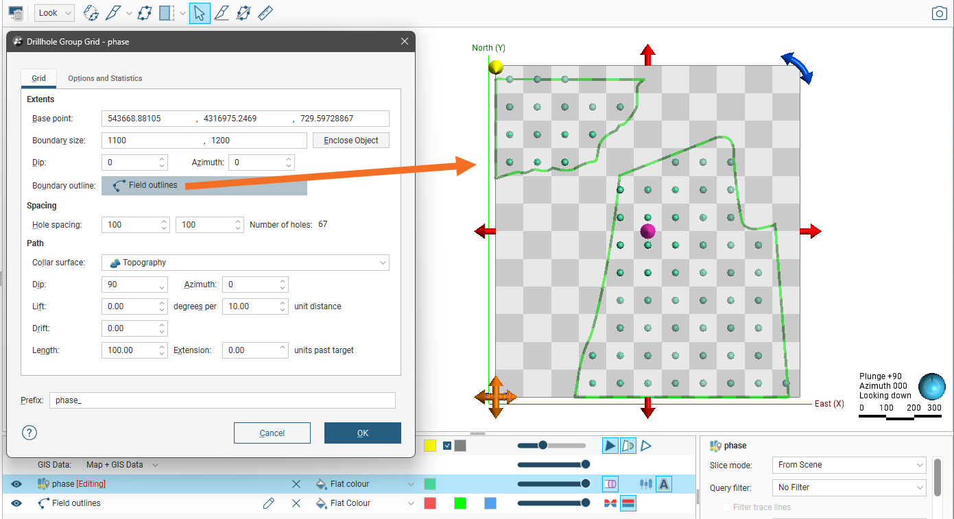
The line used does not need to be at the correct elevation; only its X and Y values are used as a boundary.
Viewing Planned Drilling Statistics
Switch to the Options and Statistics tab to see more information about the drillholes in the grid, including the minimum, maximum and average hole lengths, and the total drilling units. You can also add a note, which will be copied to the Notes field of each individual drillhole that results from the grid.
Changing Hole Ordering
In the Options and Statistics tab, you can change the order in which holes are named. Experiment with the Hole name order and Hole name position settings to determine the order you prefer. In doing this, it can be useful to set the grid spacing to result in large blocks and a reduced number of holes so you can easily see the effect of the changes these settings have. For example, here the grid has been set to show 16 drillholes and the Prefix removed in order to see the effects of changing these settings:
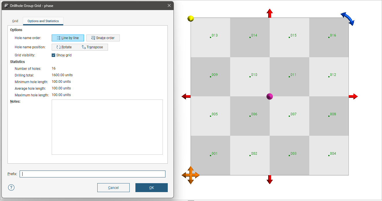
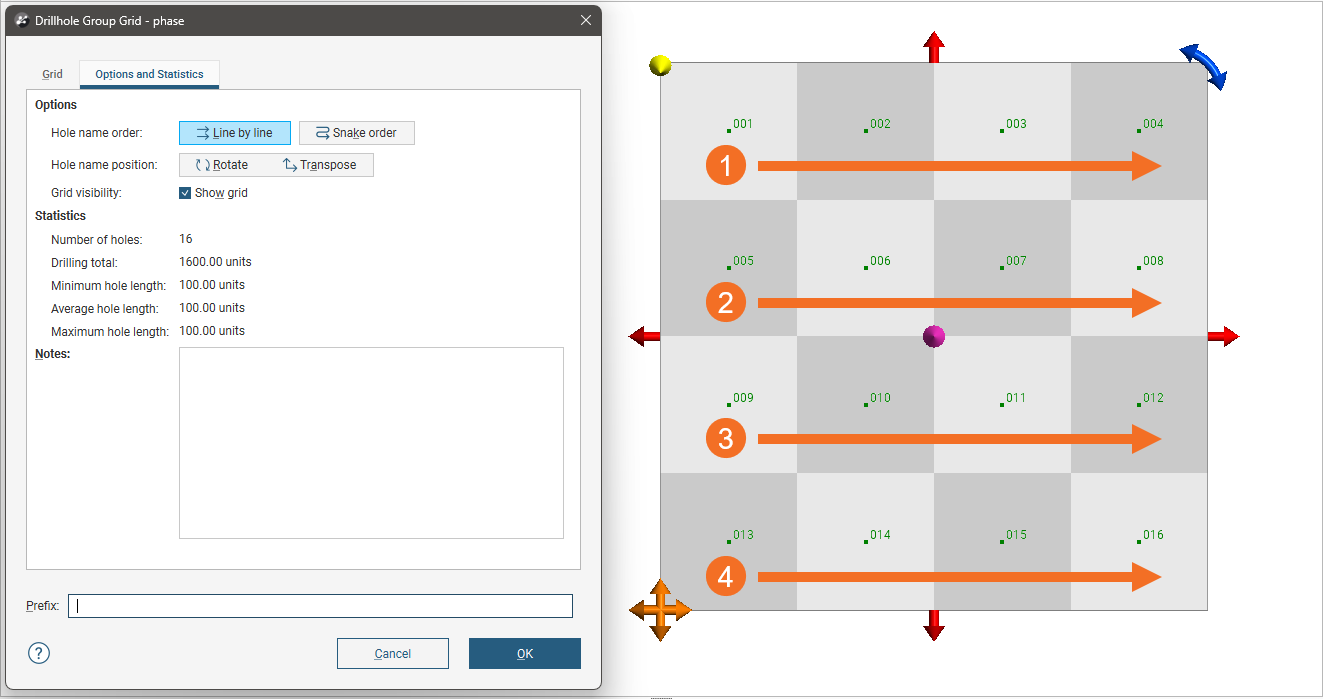
Set Hole name order to Line by line or Snake order.
- With Line by line, numbering always starts from the same side of a row.
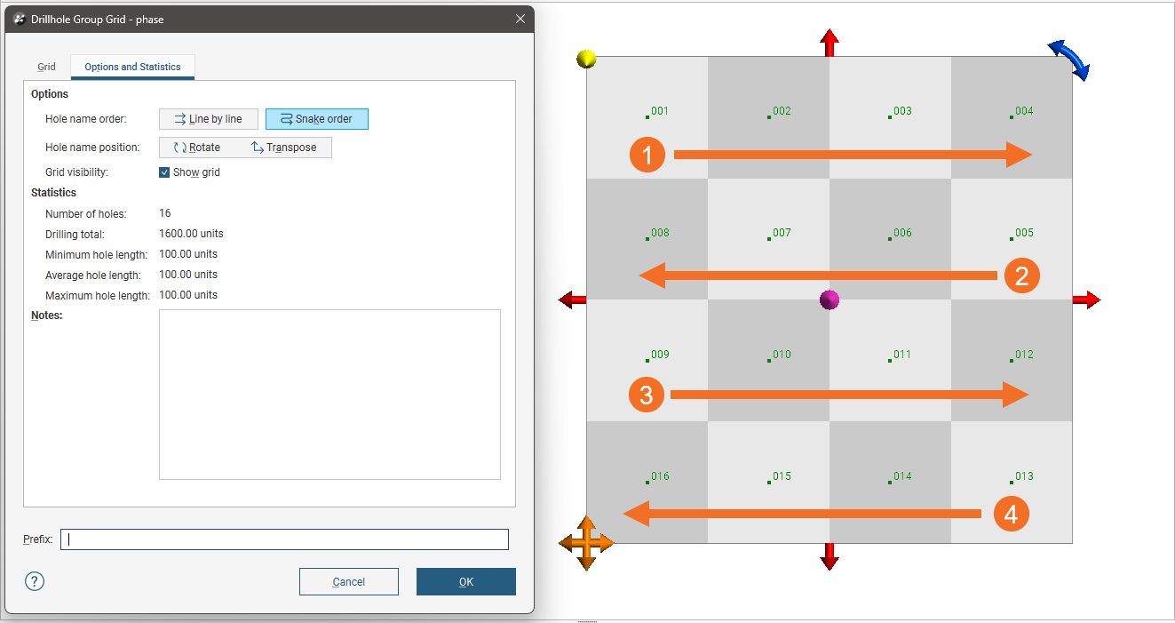
- With Snake order, numbering will change direction at each new row.
Here, the starting corner is set at the top left and the Hole name order is set to Line by line:
When the Hole name order is set to Snake order, we can clearly see how the direction of ordering changes for each subsequent row:
The Hole name position buttons are for determining where numbering starts on the grid and whether ordering proceeds in rows and then columns or in columns, then rows.
- Clicking the Rotate button moves the starting point from one corner to another, going clockwise.
- Clicking the Transpose button switches between going left (or right) across rows from the starting corner and up (or down) columns from the starting point.
Generating the Planned Drillholes
Once you have set up the grid and are satisfied with the area covered by the planned drillholes and their spacing and path, click OK to generate the new planned drillholes. They will be added to the drillhole group as individual entries. Editing them is no different from editing those created using the single-hole method.
The grid is not saved once it is closed and you cannot edit it.
If you wish, you can create a new grid to add more drillholes to the group.
Viewing Drilling Prognoses
Planned drillholes can be evaluated against any model in the project. To view drilling prognoses for a drillhole, right-click on a drillhole group in the project tree and select Drilling Prognoses. The Drilling Prognoses tab will appear:

The dropdown list contains all evaluations on the drillhole group, along with a Merged Intervals option that combines the information from all evaluations. You can copy the information displayed to your computer’s clipboard by selecting rows, then clicking the Copy button (![]() ). The information in the selected rows will be copied as tab-delimited text, which can be copied into a spreadsheet application such as Excel.
). The information in the selected rows will be copied as tab-delimited text, which can be copied into a spreadsheet application such as Excel.
Exporting Planned Drillholes
There are three ways to export planned drillholes:
Export Planned Drillhole Parameters
Exporting planned drillhole parameters exports the drillholes as a *.csv file. To export parameters for planned drillholes, right-click on a drillhole group and select Export Parameters. In the window that appears, select the drillholes you want to export. The total length will be updated as you add or remove drillholes.
You can constrain the list of drillholes to be exported using an existing Query Filter.
In Leapfrog Geo, positive dip points down for planned drillholes. To invert the dip for exported planned drillholes so that negative dip points down, tick the box for Invert dip on export.
Click Export. Navigate to where you wish to save the file, then click Save.
Export as Polylines
Planned drillholes can be exported as polylines in the following formats:
- Leapfrog Polylines (*.lfpl)
- Leapfrog Mining Polylines (*.csv)
- Drawing Interchange Polylines Files (*.dxf)
- Surpac String Polyline Files (*.str)
- Gocad Polylines Files (*.pl *.ts)
- MineSight Polylines Files (*.srg)
- Datamine Polylines Files (*.asc)
- Micromine Polylines Files (*.str *.asc)
- AutoCAD Drawing Files (2013/LT2013) (*.dwg)
- Bentley Drawing Files (v8) (*.dgn)
To export planned drillholes as polylines, right-click on a drillhole group and select Export as Polylines. In the window that appears, select where you wish to save the file, enter a file name, select the file type from the Save as type options, and then click Save.
Export as Interval Tables
In order to export planned drillholes as interval tables, you must first evaluate at least one model on the drillhole group. Once you have done this, right-click on a drillhole group and select Export as Interval Tables.
Select the evaluations you wish to include, then click Export. In the Export Planned Drillholes window, the files that will be created are listed, one each for the collar and survey table and one for each selected evaluation. Change the Base file name, if required, choose a folder in which to save the files, then click Export to save the files.
Importing Planned Drillholes
Leapfrog Geo can import planned drillhole geoscience objects from Seequent Evo. The drillholes must be single-segment holes that have no deviation or are naturally deviated. If any planned drillholes could not be imported, a message will be displayed. For more information on importing objects into Leapfrog Geo from Seequent Evo, see the Importing Data from Seequent Evo topic.
Leapfrog Geo can also import planned drillholes from files in CSV format. The columns expected are:
- A drillhole identifier
- X-Y-Z coordinates for the planned drillhole
- Azimuth
- Dip
- Lift rate
- Drift rate
- Distance
- Extension
- Target Depth
- Comment
When importing planned drillholes, you can import them into a new group or into an existing group. To import planned drillholes, right-click on the Planned Drillholes folder or on a group and select Import Planned Drillholes. If the IDs in the file are already in the project, you will be prompted to resolve the conflict:
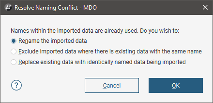
You can:
- Rename the imported drillholes. Leapfrog Geo will automatically assign new names and import the planned drillholes.
- Exclude planned drillholes that already exist in the project. Planned drillholes will only be imported if they have an identifier that does not already exist in the project.
- Replace existing planned drillholes with the imported drillholes. Use this option if you are importing information previously exported from the project and subsequently updated in an external application.
Click OK to process the file.
If there are no conflicts, the planned drillholes will be added to the project.