
Planning a Grid of Drillholes
With the grid planning method, a grid of drillholes is created using common extents and uniform spacing and path values. Once the grid is created, each drillhole in the group can be adjusted on an individual basis. This method is a shortcut for defining a large quantity of drillholes in a specific area before making any required drillhole-by-drillhole adjustments; once the grid is created, you cannot edit it.
This topic describes how to plan a grid of drillholes as part of a drillhole group. It is divided into:
- Projecting Collars Onto a Surface
- Specifying the Path
- Using a Target Surface
- Using a Boundary Outline
- Changing Hole Ordering
- Viewing Planned Drilling Statistics
- Generating the Planned Drillholes
See Drillhole Planning Groups for an overview of working with drillhole groups in Leapfrog Geo.
The Drillhole Group Window
To plan a grid of drillholes, add the data objects to the scene that you will use in defining the planned drillholes, such as any existing drillholes and surfaces that represent the collar and target locations. Next, open an existing drillhole group or create a new one by right-clicking on the Planned Drillholes folder and selecting New Drillhole Group.
Click the Grid button in the Drillhole Group window (A). This opens the Drillhole Group Grid window (B), with a grid and controls displayed in the scene (C). The number of drillholes that will be created within the grid’s extents is determined by the Spacing values, with the total number of holes indicated (D).
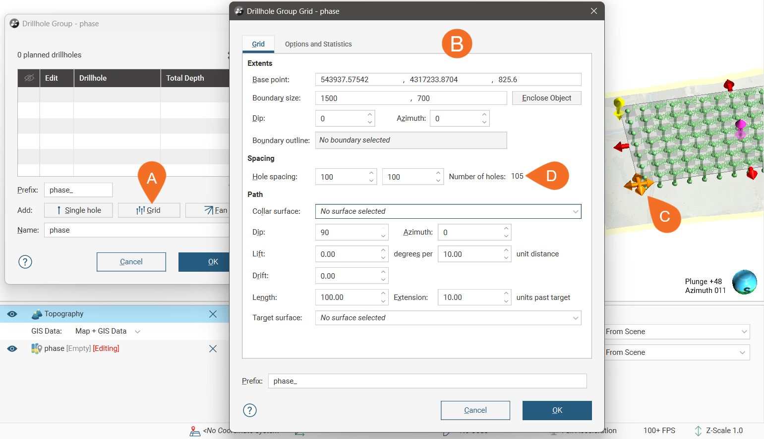
The grid created in this window is not saved in the project tree and so cannot be edited. Clicking OK closes this window and creates the drillholes specified by the grid, adding them to the drillhole group. Although you cannot edit this grid once it has been closed, you can create another grid to add more drillholes to the drillhole group.
In the scene, each drillhole that will result from creating the grid is displayed. Changes you make in the Drillhole Group Grid will be reflected in the scene.
Use the controls in the scene to set the extents of the grid:
- The orange and pink handles set the Base point values.
- The red handles adjust the Boundary size.
- The yellow handle adjusts the Dip.
- The blue handle adjusts the Azimuth.
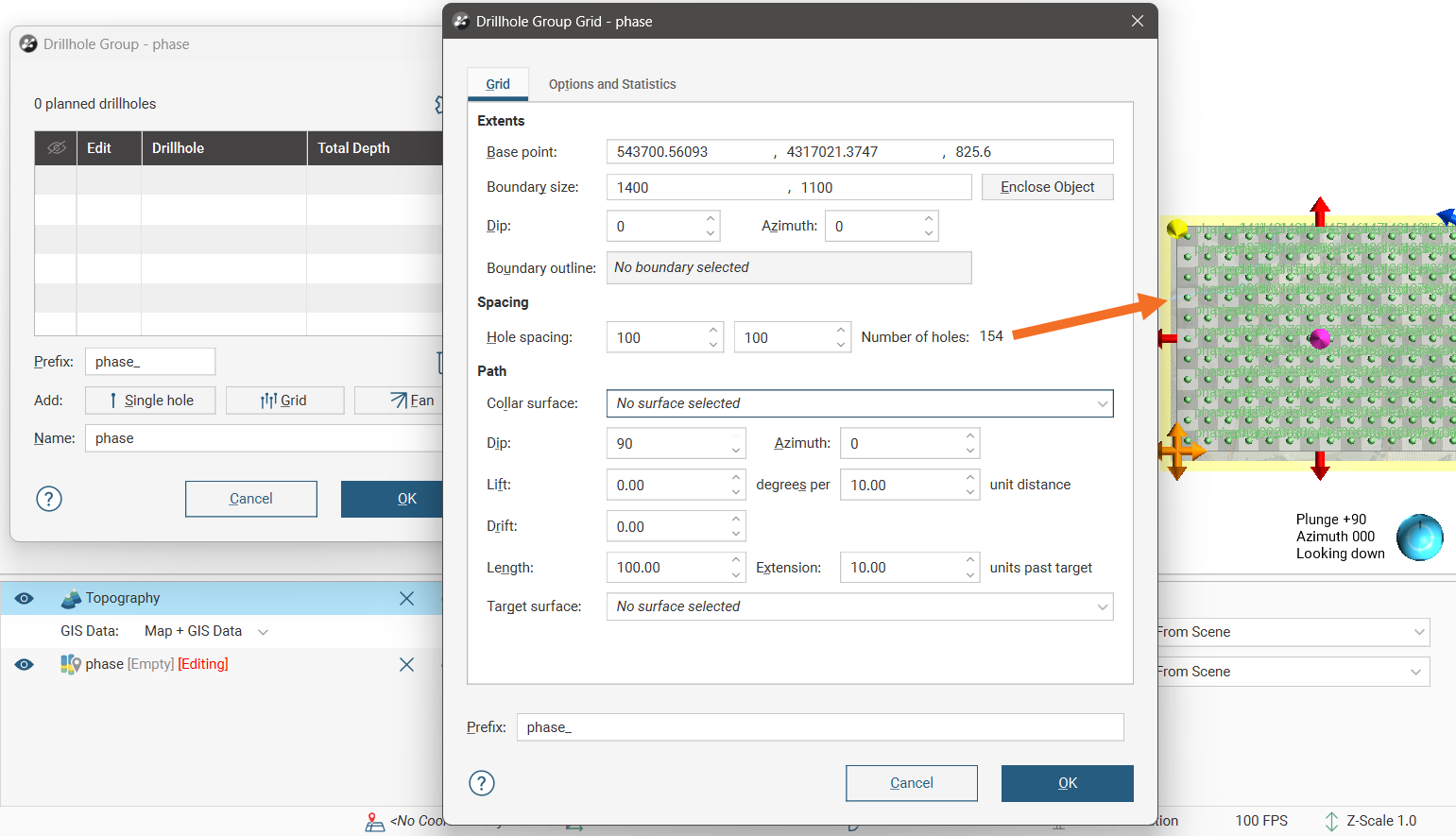
The grid extents are intended to include complete blocks defined by the Hole spacing values, and so when changes are made to the grid size in the scene, the grid will ‘snap’ so that complete blocks are maintained.
Here the extents have been adjusted to be slightly smaller than the topography (in yellow) and the Hole spacing has been adjusted to create more drillholes:
Projecting Collars Onto a Surface
To make sure all collars in the grid lie on, for example, the topography, you can choose a Collar surface from those available in the project.
Specifying the Path
The planned drillhole paths can be specified using the Dip, Azimuth, Lift in degrees per a specified unit distance and Drift.
You can specify an intended drillhole Length, and a planned Extension distance beyond the target.
Using a Target Surface
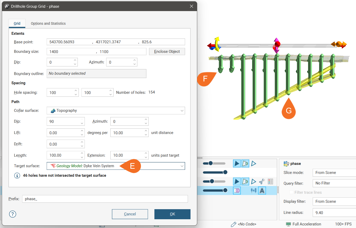
You can choose a surface or volume in the project to use to determine the target for each planned drillhole in the grid. If you use a volume as the Target surface, the last point at which each drillhole intercepts the surface will be used as the target point.
Here, we have used a vein system volume as the Target surface (E). Where the drillholes in the grid do not intercept the surface (F), the drillhole length is determined by the Length value set. Where the drillholes do intercept the surface (G), the target is the last intercept point.
Using a Boundary Outline
You can use any polyline or GIS line in the project to define the area in which drillholes will be created.
Here a polyline is used to define two areas in which drillholes will be created:
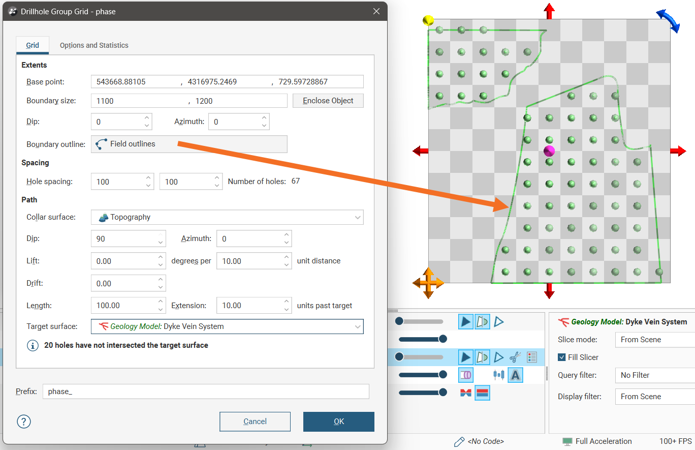
The line used does not need to be at the correct elevation; only its X and Y values are used as a boundary.
Changing Hole Ordering
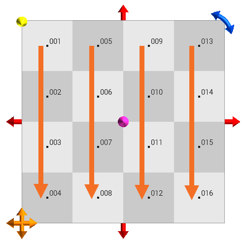
In the Options and Statistics tab, you can change the order in which holes are named. Experiment with the Hole name order and Hole name position settings to determine the order you prefer. In doing this, it can be useful to set the grid spacing to result in large blocks and a reduced number of holes so you can easily see the effect of the changes these settings have. For example, here the grid has been set to show 16 drillholes and the Prefix removed in order to see the effects of changing these settings:
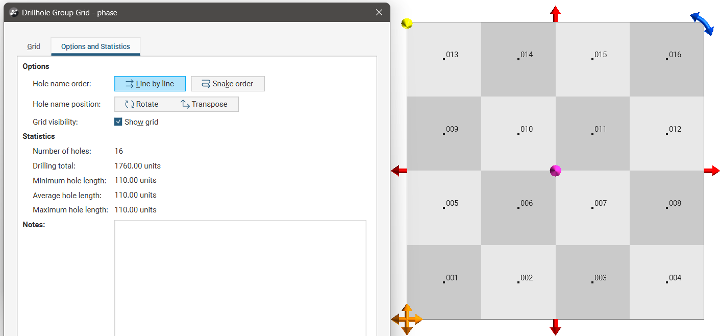
Set Hole name order to Line by line or Snake order.
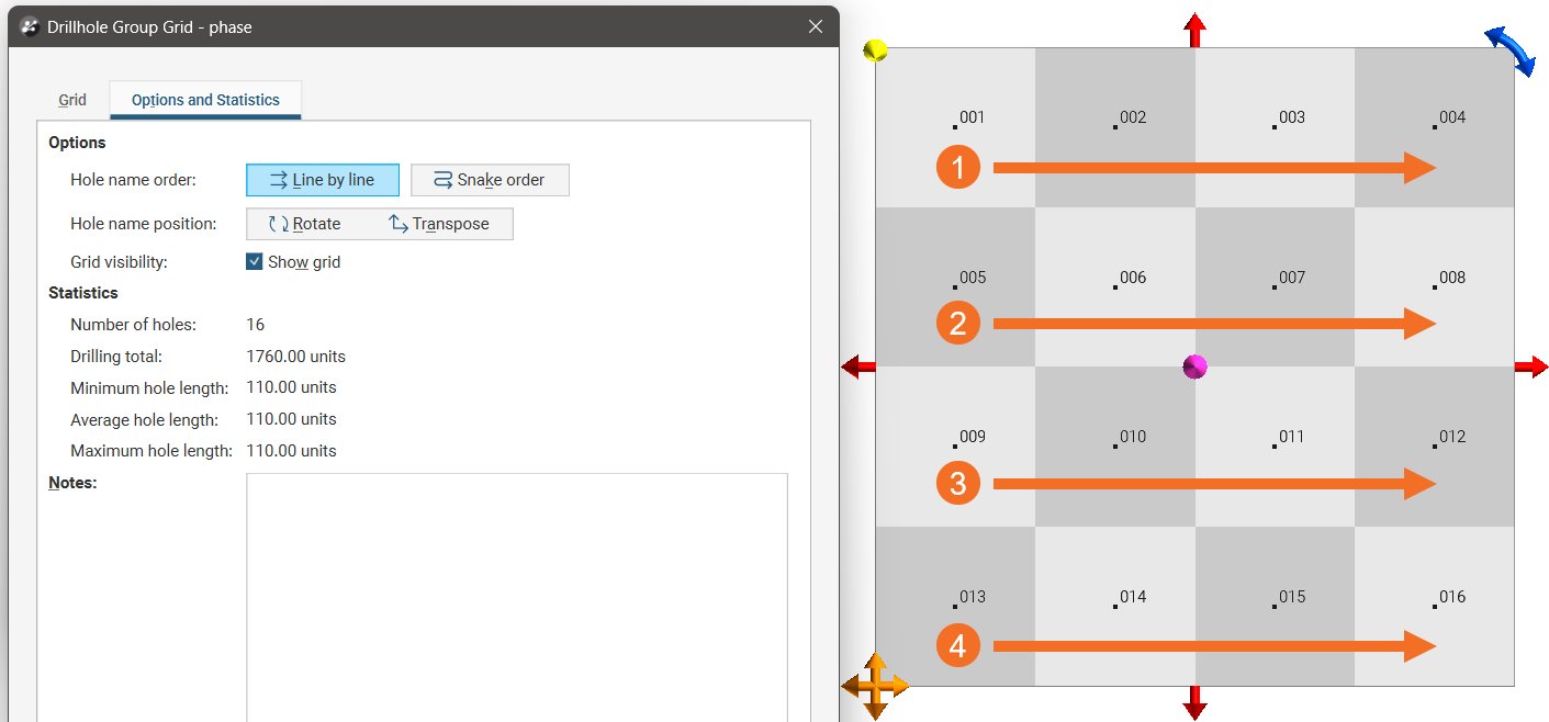
- With Line by line, numbering always starts from the same side of a row.
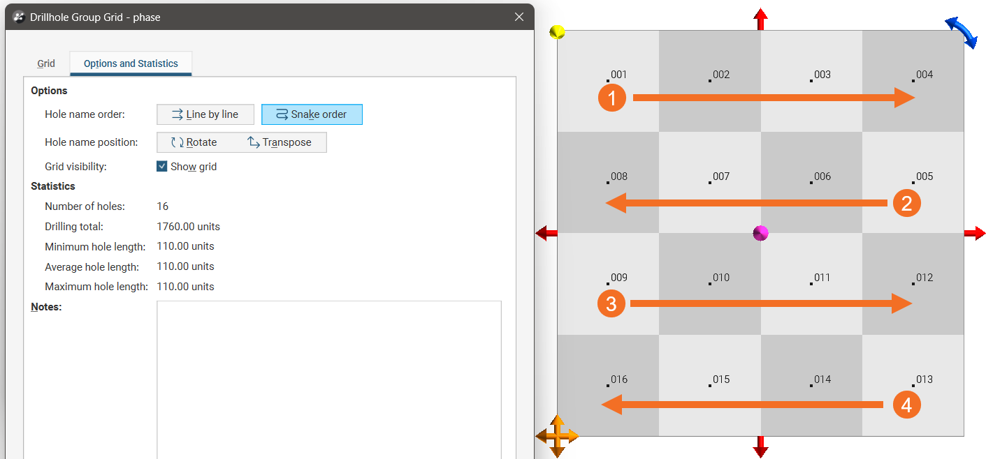
- With Snake order, numbering will change direction at each new row.
Here, the starting corner is set at the top left and the Hole name order is set to Line by line:
When the Hole name order is set to Snake order, we can clearly see how the direction of ordering changes for each subsequent row:
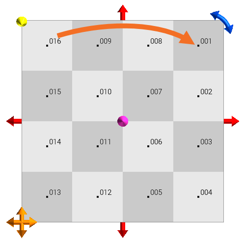
The Hole name position buttons are for determining where numbering starts on the grid and whether ordering proceeds in rows and then columns or in columns, then rows.
- Clicking the Rotate button moves the starting point from one corner to another, going clockwise.
- Clicking the Transpose button switches between going left (or right) across rows from the starting corner and up (or down) columns from the starting point.
Viewing Planned Drilling Statistics
Switch to the Options and Statistics tab to see more information about the drillholes in the Statistics section, which contains information useful for making decisions about the planned campaign:
- Number of holes: How many holes will be created according to the current settings
- Drilling total: What total linear distance will be drilled if the plan is executed
- Minimum hole length: The length of the shortest planned drillhole
- Average hole length: The mean length of the planned drillholes
- Maximum hole length: The length of the longest planned drillhole
Notes provides a place to record freehand comments relating to the planned drillhole group. The note will be copied to the Notes field of each individual drillhole that results from the grid.
Generating the Planned Drillholes
Once you have set up the grid and are satisfied with the area covered by the planned drillholes and their spacing and path, click OK to generate the new planned drillholes. They will be added to the drillhole group as individual entries. Editing them is no different from editing those created using the single-hole method.
If you wish, you can create a new grid to add more drillholes to the group.